 Cassandra.org
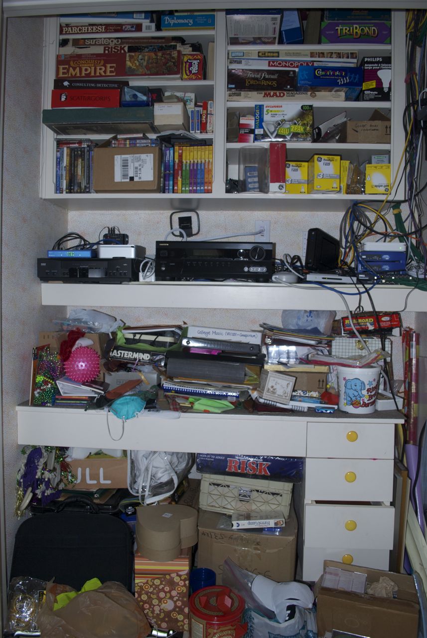
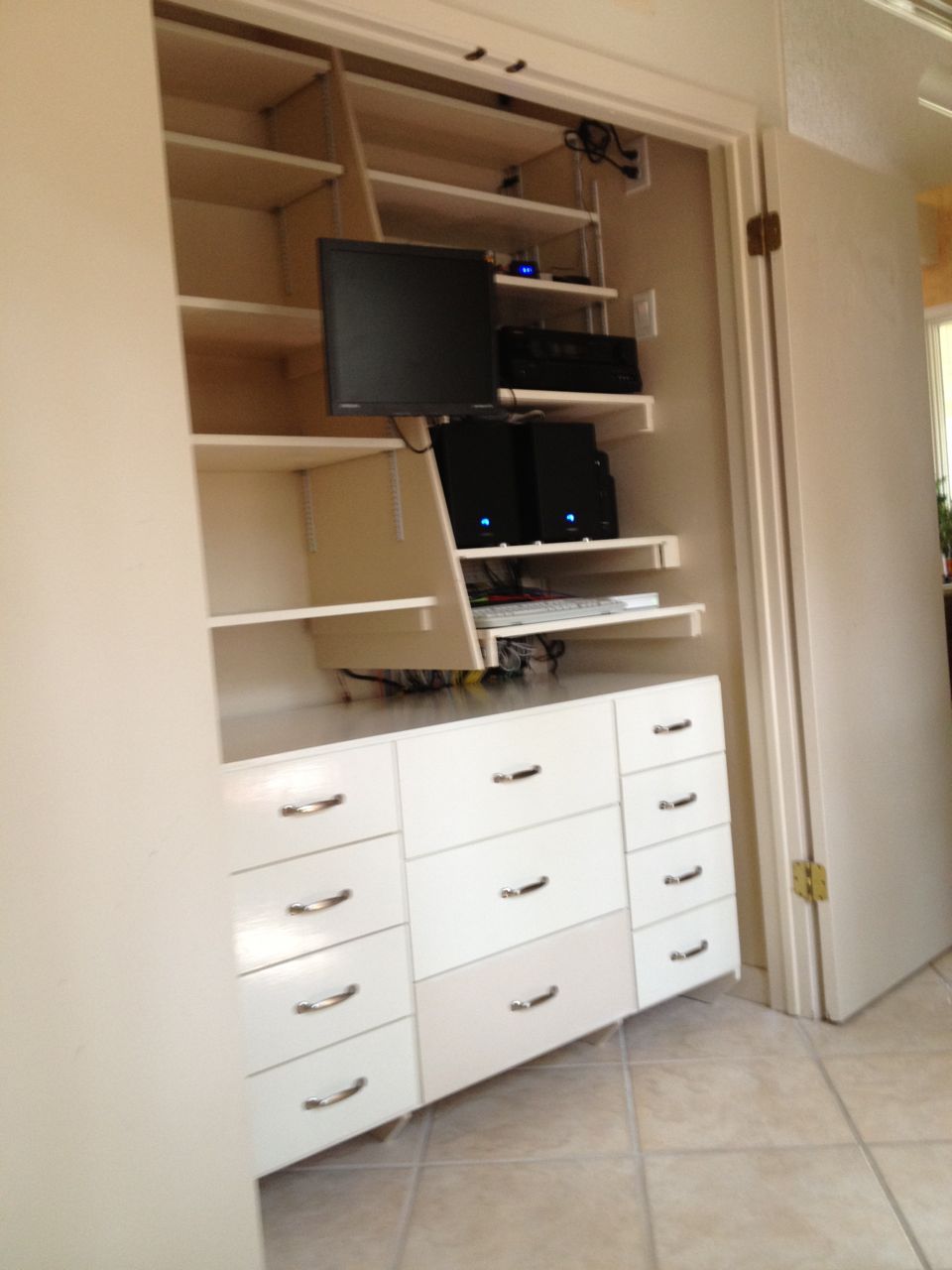
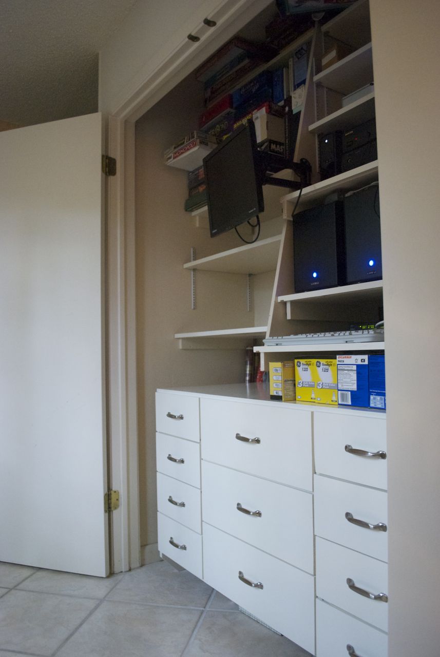
Before
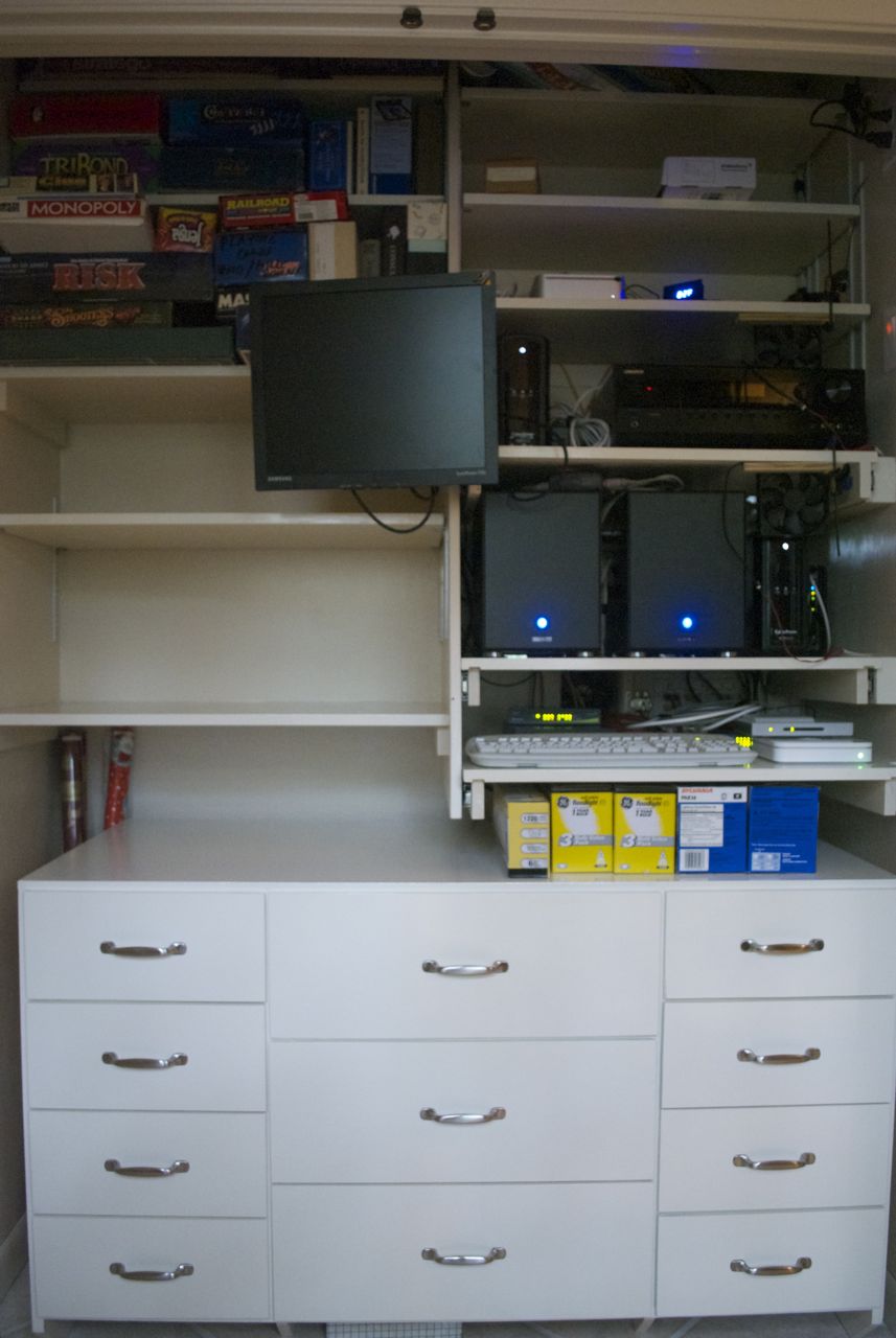
After
Story
In our house, there is a large closet just off the kitchen that one of
the previous owners used as a sewing closet. It has a few, narrow
shelves up high, and a sewing desk with drawers such that with the two
closet doors open you can sit at the desk and sew. Not having much
sewing to do ourselves, this closet stored our games, light bulbs and a
lot of work-related miscellany. Back when I wired the house with cat 5e
cable to all the rooms many years ago, this closet is where I
terminated all the cables. Thus, this became the network closet with
the main Ethernet switch as well as the cable modem, router and
wireless access point.
More recently, when I did the Home Theater
Project I also put all the home theater equipment in this
closet. While functional, it became a bit of a mess in there, and with
my wanting to move the servers from the Home Server Build Project
in there, it was time to reconfigure this closet to be more functional
as a server and storage closet than a sewing closet. This page
describes the conversion of the closet.
Overview
Now, let me first address the question you might be asking yourself:
-
"How does cleaning your closet turn into something you call a
"project"?
- Demolition of the old sewing desk and (way too small) shelves;
- Relocation of the electrical outlets;
- Relocation of all the Ethernet cables;
- Relocation of all the home theater cabling;
- Adding additional support structures to support the new shelves;
- Adding adjustable and movable shelves for easy access to the connections on the back of the computers and home theater equipment;
- Installation of a vent and temperature-controlled fan in the wall for cooling;
- Addition of internal lighting and switch;
- Mounting a monitor and keyboard tray for ability to work on servers;
- Building a new cabinet for storage;
Requirements and Specifications
The things the server closet will need to have room to contain:
- Main house server (cameras, SSH, OpenVPN, web server)
- Network storage server (backups and shared files, images, movies, music)
- Home Theater server (currently a Mac Mini)
- Audio/Video Receiver (currently an Onkyo)
- Cable Modem
- UPS (uninterruptable power supply)
- Router/Wireless AP (currently an AirPort Extreme)
- 24 Port of Gigabit Ethernet switch
- 4 Port POE Ethernet switch (for cameras)
- HDHomeRun (converts TV over antenna to IP stream)
- VCR (yes, long story)
- Small LCD Monitor (for working on servers)
- Keyboard/mouse for working on servers
- Games
- Teaching supplies
- Light bulbs
- Miscellaneous, undetermined stuff
The features the server closet should have:
- Good air flow/cooling (maybe remote temperature sensor)
- Good cable management
- Place to mount two double outlets for all the house Ethernet ports (RJ-45)
- Place to mount HDMI single outlet
- Place to mount double outlet for home theater speaker wires
- Place to mount single outlet for extra speaker wires
- Making rear of components easily accessible and visible
- Extra shelf space for non tech things
- Drawers for non tech things
- Shelves should be adjustable height
Initial (abandoned) Design
My original plan was to have a section of shelves that would completely
swing out as the way to get full and easy access to the rear of the
electronic components. I did all sorts of research on the strengths of
hinges that would be needed to support the weight of the components and
figured 4 or 5 door hinges would easily suffice.
However the complication was that this would have to lie on an
infrastructure that could also support that load, which effectively means
that the shelving structure would have to be part of the main house
framing. If the existing studs were in the exact locations I needed for
the dimensions of the shelves I needed, this would not have been too bad,
but the odds of that were low, and the reality of their locations meant I
would need to open up 3 walls and the ceiling to be able to build a
suitable frame.
As I was designing such a structure and mapping out the work, this
creeping thought started to gnaw at me: Might I spend more time
building this structure than the time it will save me from the
inconvenience of a slightly inferior solution? After some time, the
answer to this question became quite clear, though I am sure it would
have been clear to saner people much sooner than it did to me. I was a
little bit enamored with the swing-out shelf idea.
Design
Instead of swing-out shelves, I decided I would add a few sliding
shelves. This would not be ideal, but would make it a bit easier than if
the shelves were fixed. Interestingly, once I turned to this decision,
the entire design of the closet came to me in an instant, and the
resulting solution became super simple to build (conceptually). There's
still a lot of work to do, but there was little uncertainty to how I would
build the shelves and cabinet and that this would work with minimal
surprises.
Now being on the track of simpler solutions, I also abandoned my initial
idea of having a built-in cabinet and opted for stand-alone cabinet that
would slide into the closet. That wound up being a separate project I
call the Closet Cabinet
Project.
The Planning Phase

Initial Design - Side View
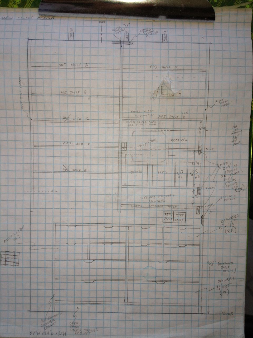
Initial Design - Front View
I mostly planned this before I was back home full-time when I was
visiting for a couple weeks. The plans are also a derivation of the
initial ideas I sketched when planning to have swing-out shelves. The
final result is close to this, but not exactly like this. These
sketches also reflect some of the changes I made as I went along and
faced various surprises and unforeseen constraints.
The Waiting Game

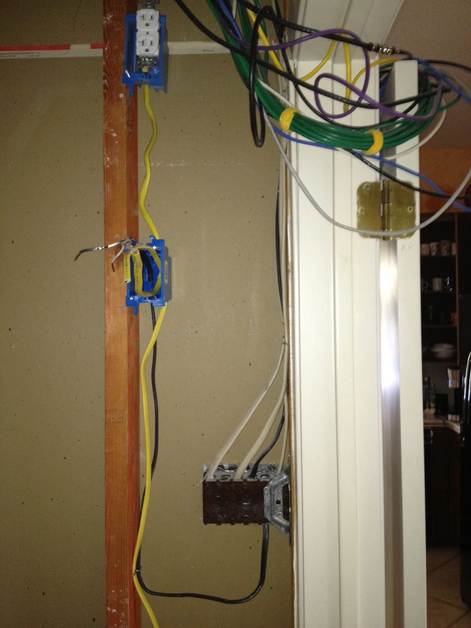
Example of Existing Wire Chaos
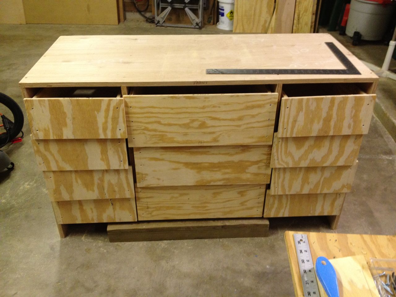
Cabinet after Dry Fitting before closet started
Besides the finishing (sanding and painting), the Closet Cabinet was
completed first as I waited for my wife to have time to go through and
empty the closet of her things. I was also busy with the design work
on the New Decks Project while I
waited. However, while working on the cabinet, I rough cut all the
pieces I will need for the shelving and bought the rails for the
sliding shelves. I wanted to combine all the final sanding and
painting because both these steps require me to reconfigure my workshop
(a.k.a., the garage). You do not want lots of sawdust floating around
while painting.
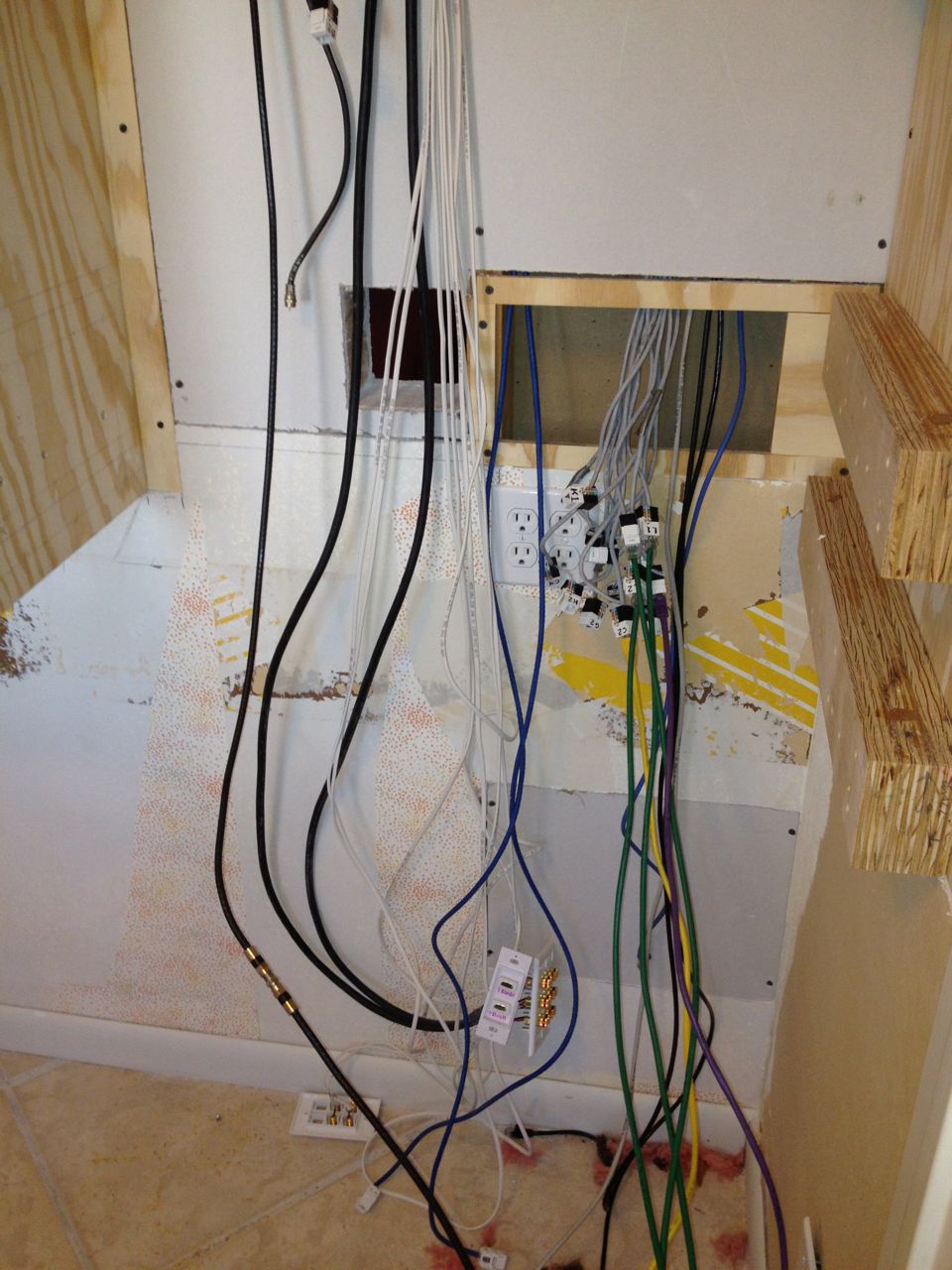
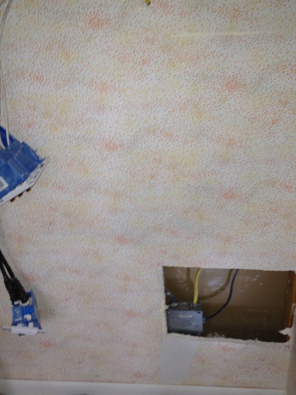
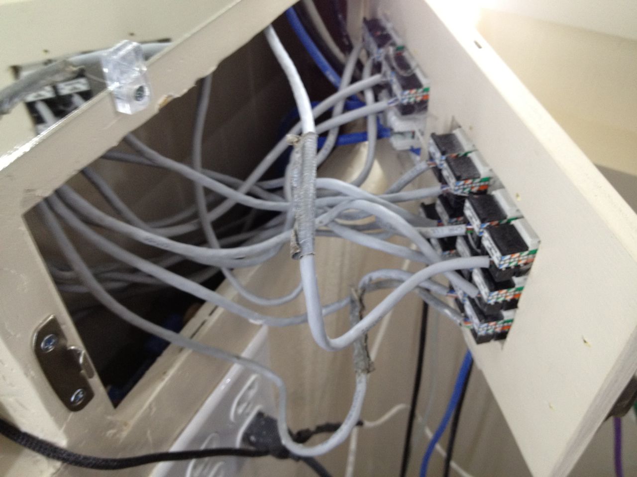
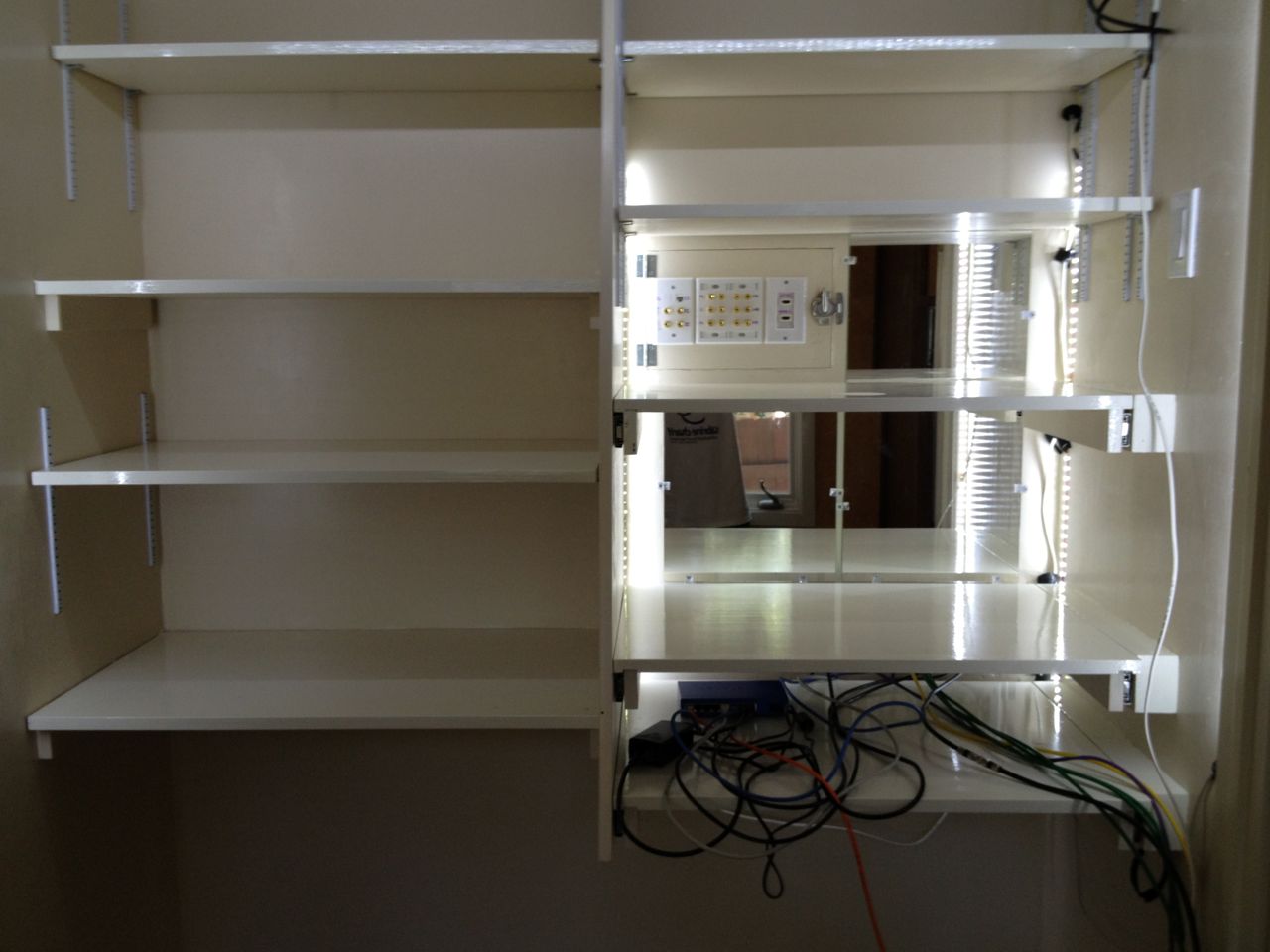
Preparation
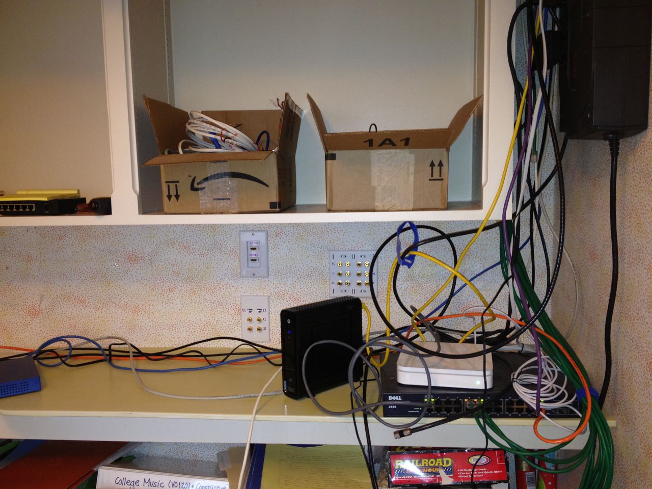
After reducing to the minimum required wiring.[
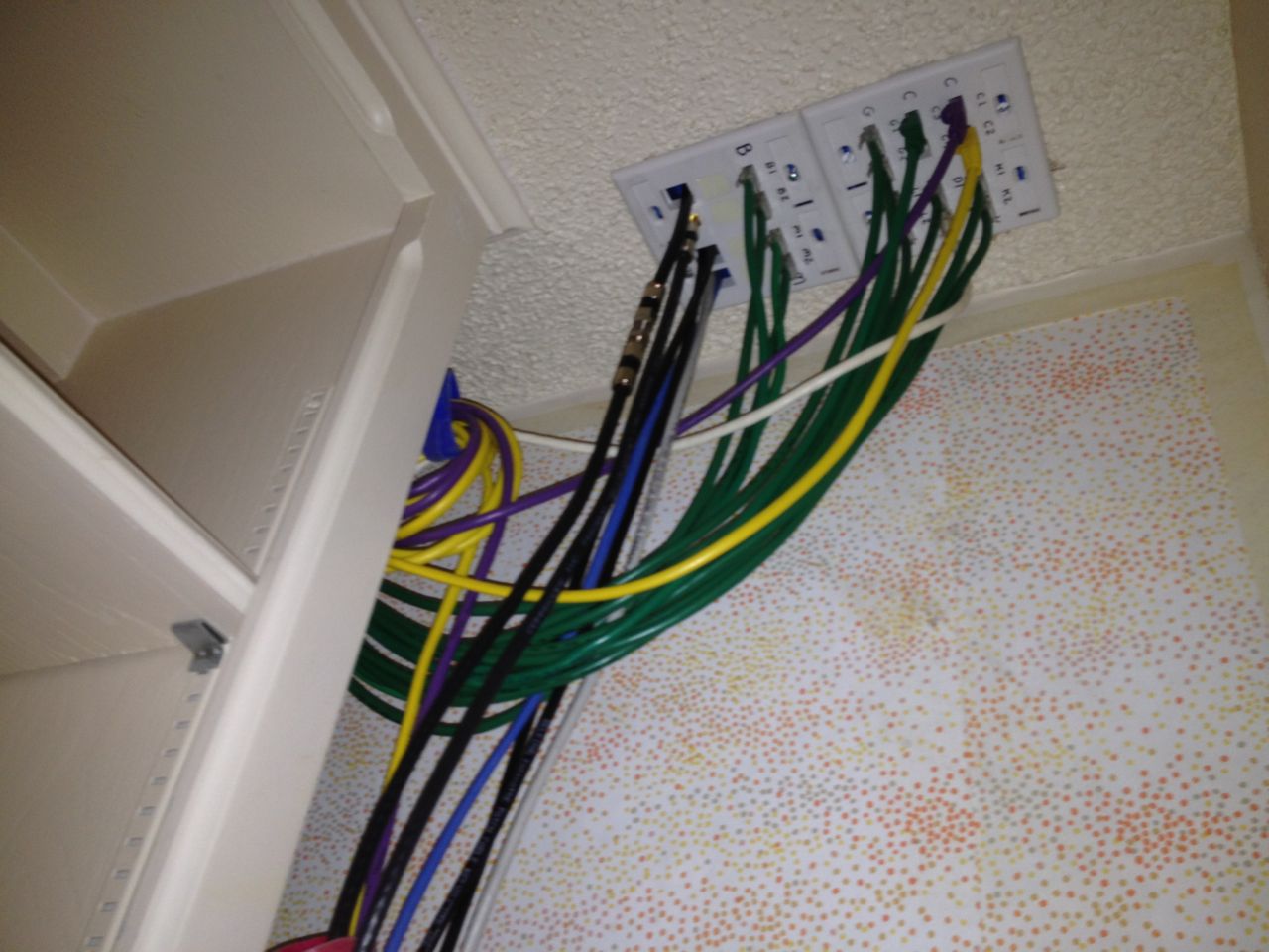
Existing panels where all network connections come into the closet ceiling.
The first complexity was how to keep the Internet connection working
during the duration of the project. We could live without the
home theater equipment, but not the Internet and I did not want to do
any major re-routing of wires. The plan was to pare it down to the
absolute minimum I would need and try to run all the cables to a nearby
table. I slowly began to disconnect and remove the non-essential
components and cables, which was a bit of a discovery process since I
had not thought about exactly what was and was not critical parts of
the infrastructure. This did help me plan the future setup in terms of
what did and did not need to be on backup power (on a UPS).
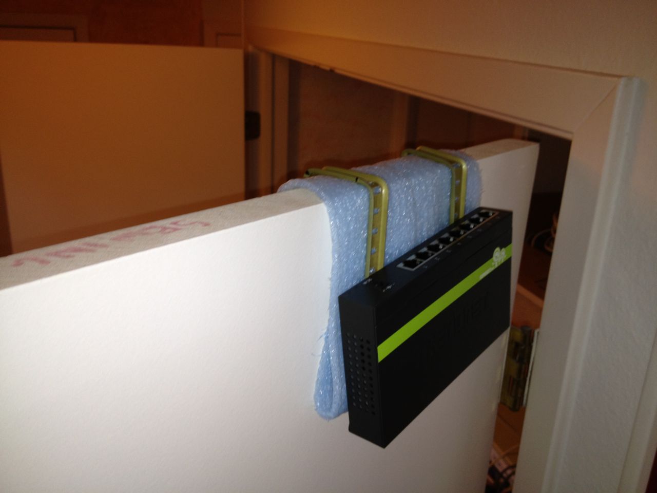
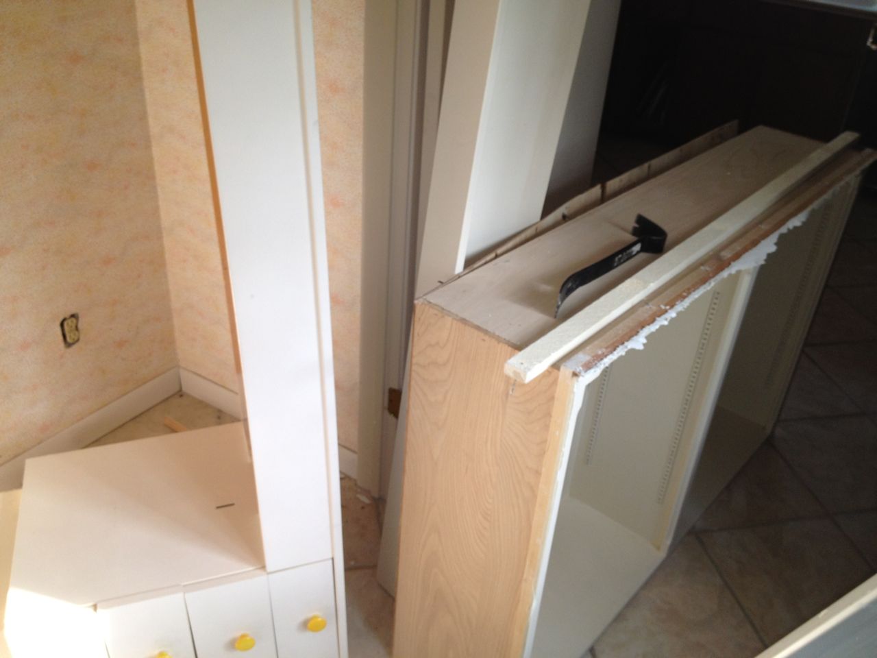
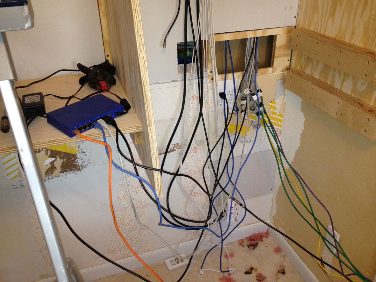
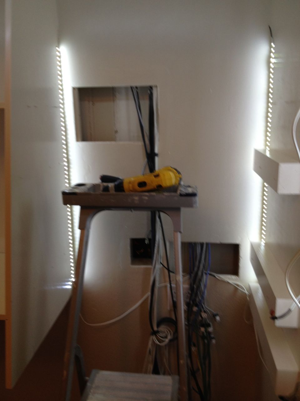
Improvised hanging switch for shorter cables.
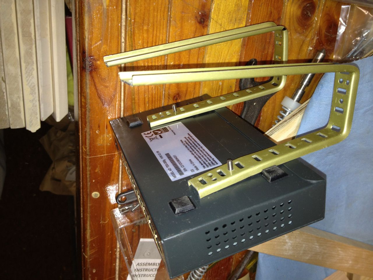
Improvised switch bracket.
For the most part, I was able to route the cables out of the closet to
a nearby table, but there were a few wires that were not long enough to
reach. I did not have the cables to lengthen their reach, nor did I
want to invest in them and/or wait for them to be delivered. I had to
improvise a solution by hanging a switch on the top of the door. I
used some old shelf brackets, tapped some holes for screws and added
some padding so it would not scratch the door. On the nearby table
where I assembled all the network gear, I ran an extension cable to
power it from a different room. I would need to be doing electrical
work in the closet and I did not want to have to be without the
Internet while I had the closet circuit breaker off.
The Demolition
The old desk and cabinet removed from closet.
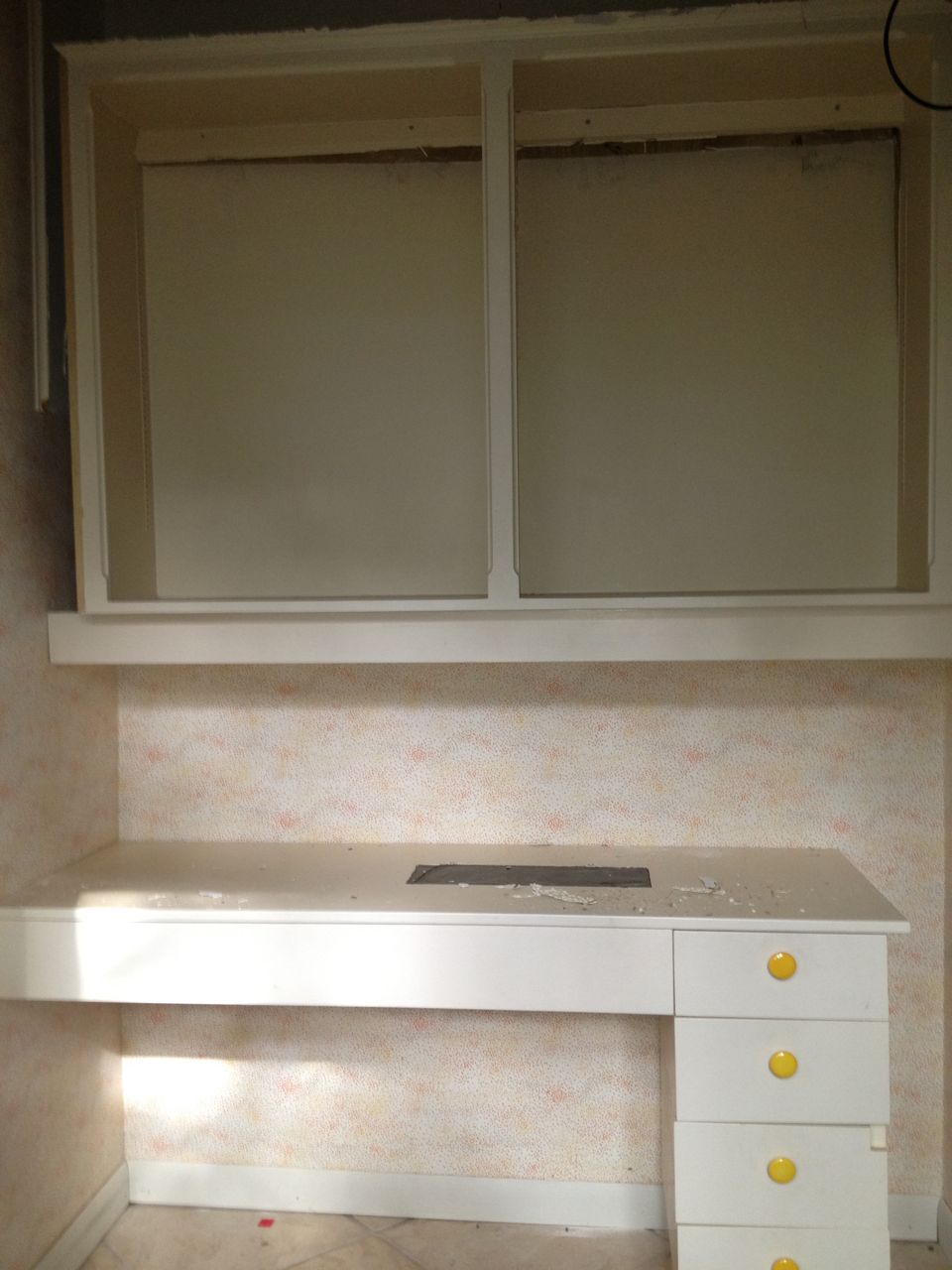
The old desk and shelves after .
After the closet was cleared out and the temporary wiring changes, it
was time to begin the physical work, starting with removing the old
desk and shelves. Surprisingly, the shelves were held up by exactly
two nails. I am not a fan of nails and I would never think to use only
two nails for any entire shelf assembly, but the shelves were still
standing and the nails were not so easy to remove. I tend to
over-engineer structural things.
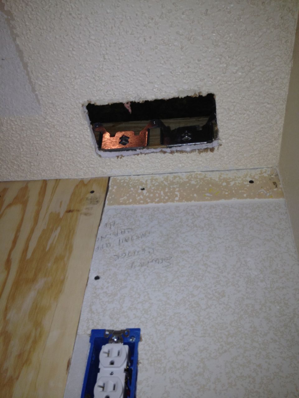
A Simple Start

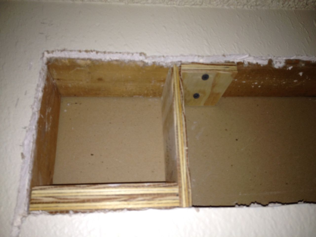
After new junction box and wall outlet installed.
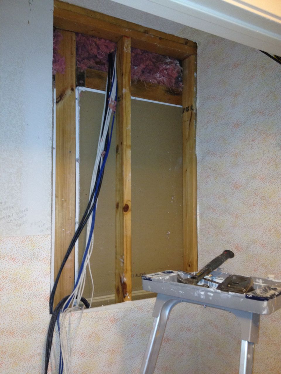
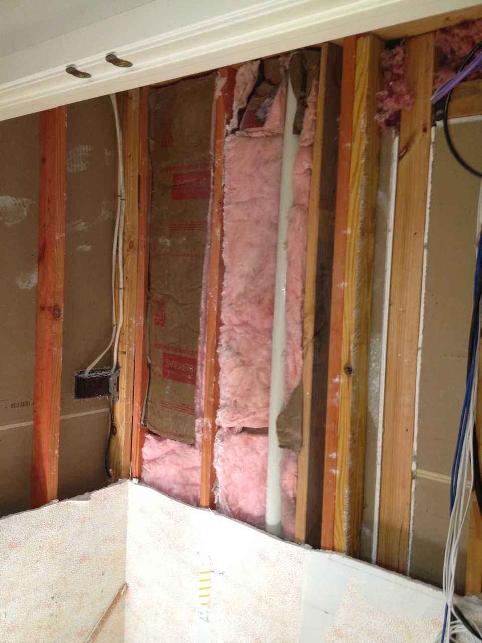
Wall boards removed and existing home theater wiring exposed.
Next came removal of the wall boards in the area where the wiring would
be. This needed to be done because I was going to be adding additional
wiring access and also because I needed more visibility into the wall
structure to help refine the plans for installing the shelving. One
surprise I found after removing the old desk was that there was another
electrical outlet behind the desk. There already was an electrical
outlet in the closet on the right side wall, and it was only a couple
feet away from this discovered one. The desk drawers made this outlet
inaccessible, so I suspect that they added the second one after the
fact once they realized the mistake. Two electrical outlets in a
closet otherwise does not make sense. Fortunately though, this
actually simplified the electrical work I needed to do (for the
moment). If I added a junction box where this hidden outlet was, I
could easily add a new outlet higher up on the same wall with little
effort since I already had the wall open.
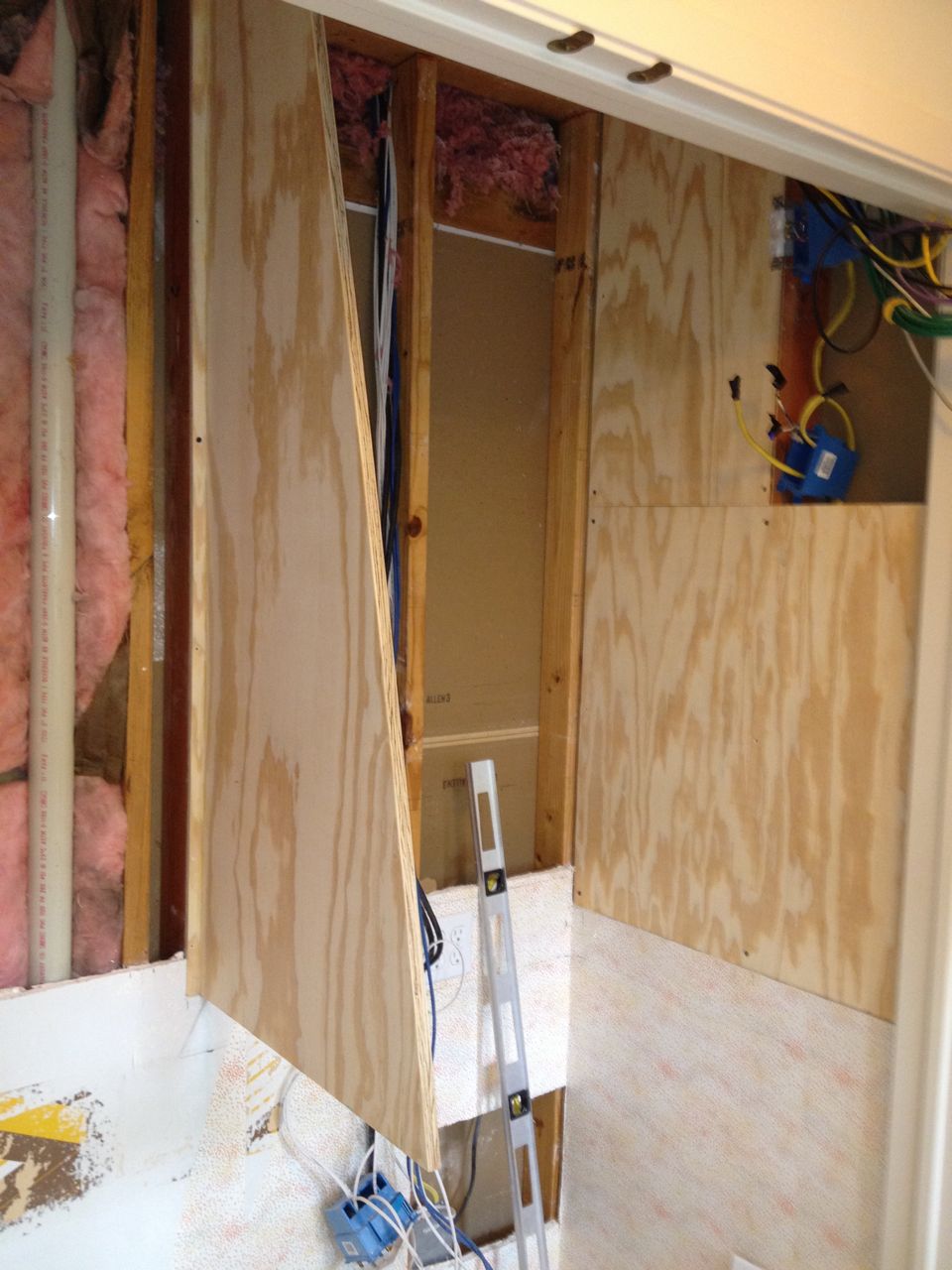
The Demolition Escalates
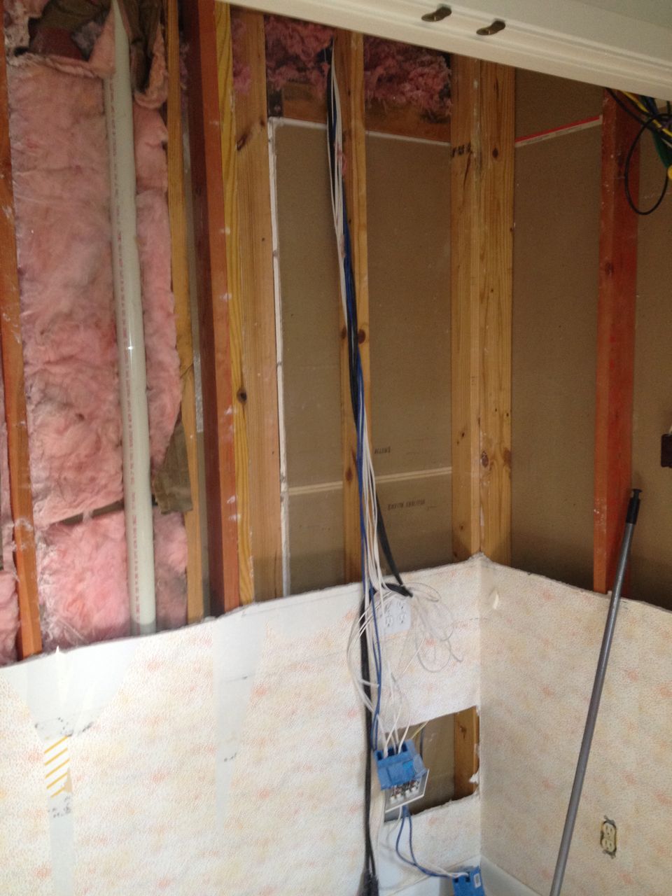
Wallboard removed: right side of closet.
Wallboard removed: left side of closet.
My initial plan for supporting the shelves was to screw in some pieces
of plywood to the studs. I did not like this solution because that
leaves you with a "wallboard sandwich" where there is a (useless) piece
of wall board between the studs and the plywood. I also realized I
needed to open up more of the wall to see how to affix the center shelf
support. It was this point in the project where I saw a path toward
incremental escalation and decided to meet it head on and strip the
entire closet of wall board (except the lower part). There would be no
piecemeal surprises and I would have a solid plywood on stud support
structure.
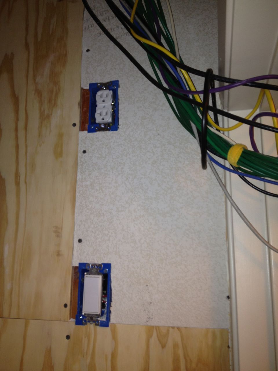
Additional Electrical Work
New outlet and switch for lights and fans.
The outlet I move up was to be used as the main one to power all the
equipment, but I planned to add some form of lighting solution and the
cooling fans. Both the lights and fans would be located near the top
of the closet and I preferred not to have a long cable run and
additional cable congestion. So on the right side wall, I added an
outlet about 6 feet off the ground, where the bottom outlet would be
controlled by a switch. The switched outlet would allow me more
flexibility on lighting solutions, which I only had a vague idea about
at this time.
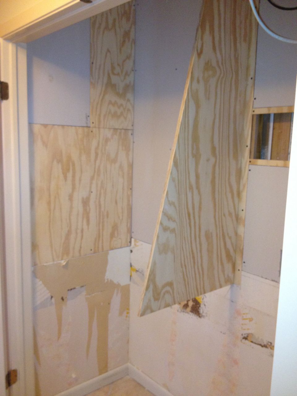
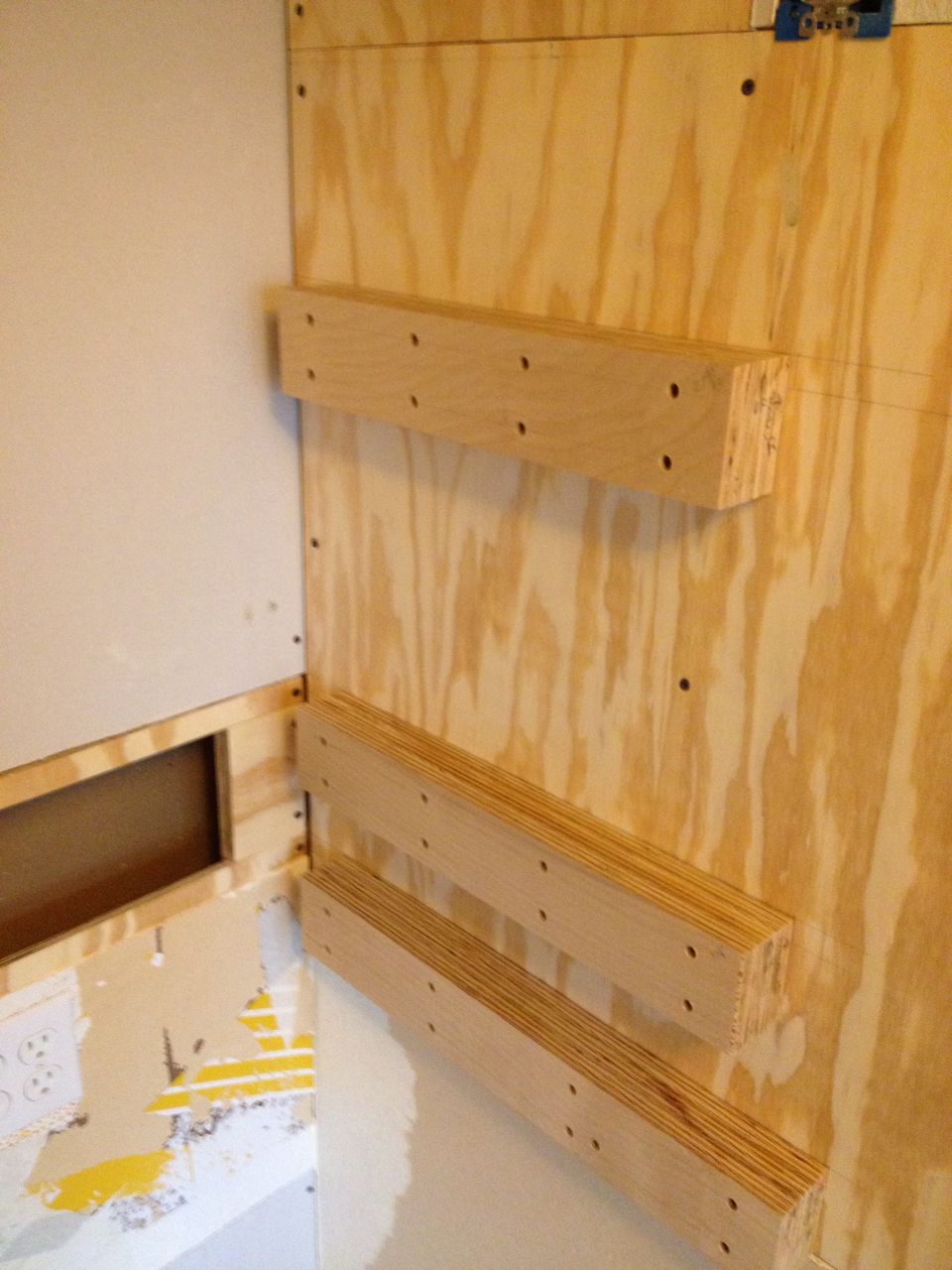
Shelf Support Structure

Close-up of center shelf support structure.
With all the behind-the-wall electrical work done, I was ready to add
the most critical pieces of the project: the shelf support structure.
Half-inch plywood against two walls and a central piece of
three-quarter-inch plywood would be taking the full weight of what
would be on a total of 12 shelves. Putting plywood on the side wall
studs was simple, but I needed a more clever solution for the central
support. I used a dado joint on a strip of wood so that I could attach
the support to this strip and then easily nail the strip to the
studs. I also added a similar strip to the top to be able to screw into
the ceiling joist for added support. The shelf brackets will fail long
before my shelf support structure does.
Left side of closet after shelf supports installed.

Right side of closet after shelf supports installed.
You will notice that the center support is tapered, which matches the
decreasing shelf widths as you go upwards. This is part of the design
because with the door not going to the ceiling, getting things on the
top shelves require maneuvering room. Originally, the design had the
two side plywood pieces in the same tapered shape, but I decided it
would greatly simplify the sheet-rock work if I just used rectangular
pieces instead. The trickiest part of installing the center support was
ensuring that it was level and straight. Since the plan was to have
sliding shelves, if the center support and the wall were not parallel,
a sliding shelf would not work: you cannot (easily) build a sliding
trapezoid. here the complications though:
- the walls themselves are not parallel;
- the center support plywood is slightly bowed; and
- the furthest protruding part of the center support needs some side-to-side movement stability.
Note that the other main benefit of having plywood on
the wall was to add flexibility for mounting anything else that would be
needed without having to worry about finding a stud.
Fan Boxes
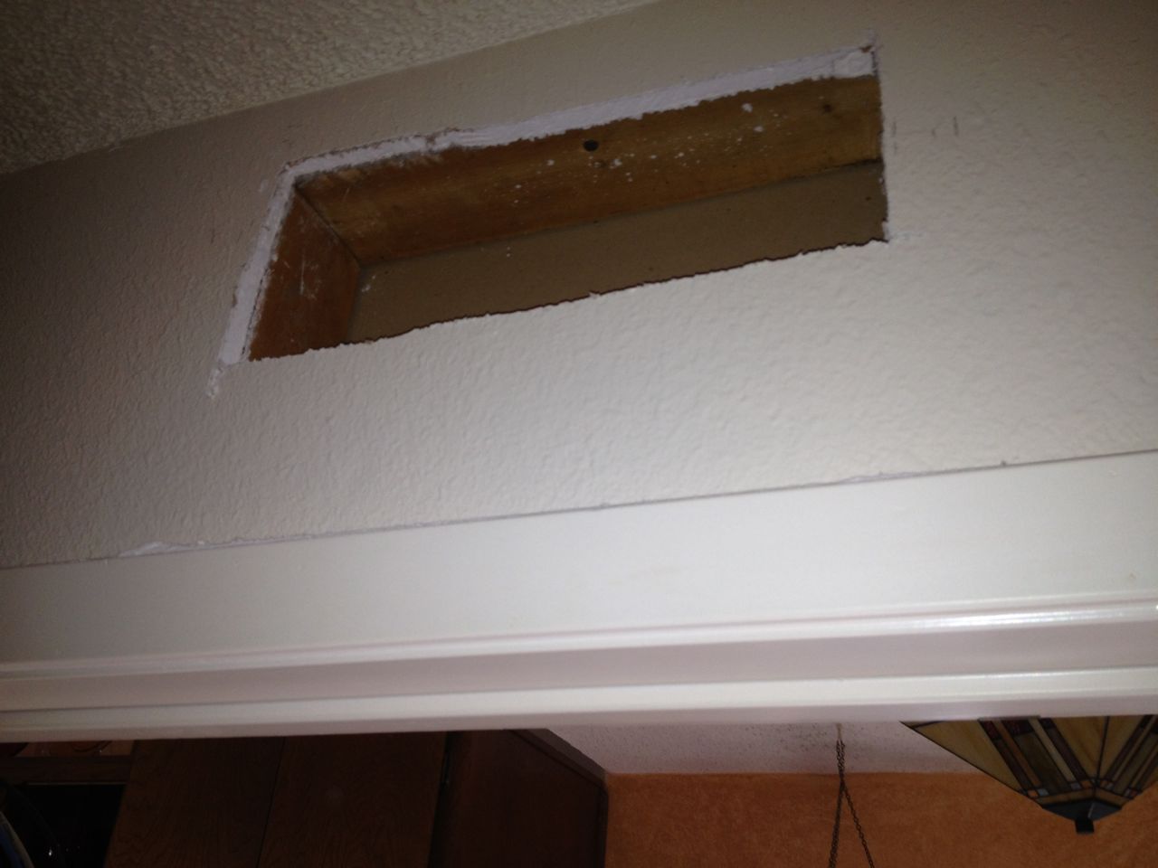
Initial hole over closet doors for outflow fan.
When I first put the cable modem and network switches in this closet, I
put them on a high shelf because that was closer to where they came in
on the ceiling and I also wanted them to be as out of the way as
possible. Because the heat generated would get trapped, over the years
I burned out two different Linksys switches. I move that equipment to
a lower shelf and that helped a lot. But the addition of the home
theater receiver and a new cable modem only added more heat to the
closet. With my plan of moving two servers into this closet, I had
to have a cooling solution.
Fan box installed for outflow fan.

Fan box for inflow fan.
I found a nice simple temperature
controlled fan controller and with help from my wife decided to add
both an inflow and outflow to promote good airflow. This mean poking
two holes in the wall, and trying to do so in as non-intrusive a way as
possible. I also wanted to ensure that the fans sucked the air from
the closet and not from inside the walls. Thus, I created simple
plywood boxes to channel the air.
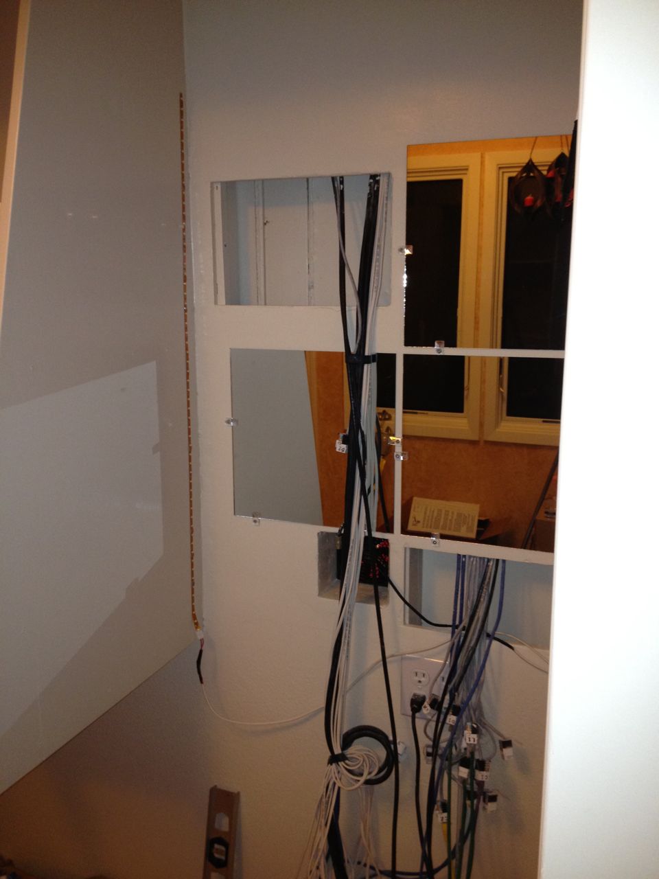
Access Panels
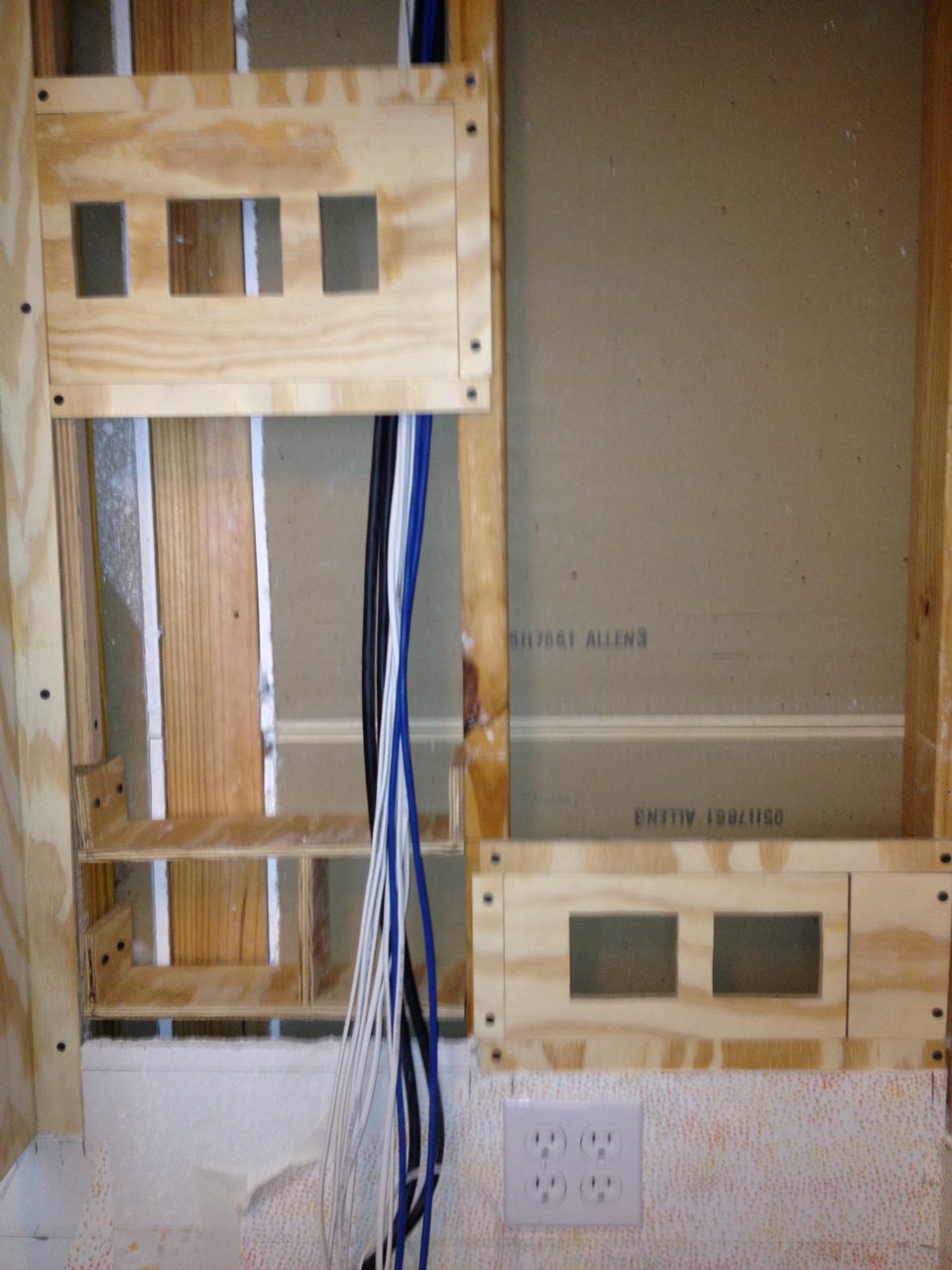
Access panels installed.

Laying out the access panels.
Once I had the walls opened and contemplated the annoyances I always
face when adding wires to this closet, I decided to make my future work
simpler by putting in hinged access panels instead of mounting things
to the wall. The patch panel plates would mount to a door that could
be open and closed to get at the back side of them as well as providing
a wide access to wall cavity to more easily find cable drops.
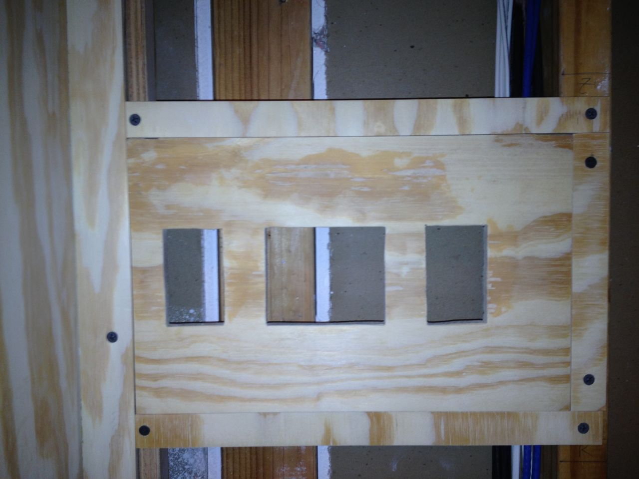
Close-up of the home theater cable access panel.

Close-up of the network cable access panel.
The tricky part here was making the access panels big enough to house
all the needed cables, but located so that opening and closing them did
not interfere with the shelves. I was hoping to have room to have space
for expansion, but under the constraints, it was all I could do to
provide the space for the already needed wiring.
Wallboard Installation
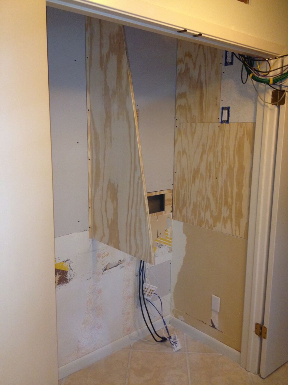
Right half of closet after wallboard installation.
Left half of closet after wallboard installation.
With all the electrical work, support structure, fan boxes and access
panels in place, it was time to cover what remained with wallboard.
This is always the turning point of a project. For the first time you
can start to see the final result begin to take shape: the solution
turns from crude pieces to a more coordinated and refined whole.
New switch and outlet after wallboard installation

Outflow fan hole.
Although the fan boxes where installed, I had never actually poked
through the wallboard to the external side. I wanted to wait until the
last possible second before I made changes that were visible outside
the closet. Wanting to wrap up all the sheet-rock work0, now was the
time to take the plunge.
Change of Plans
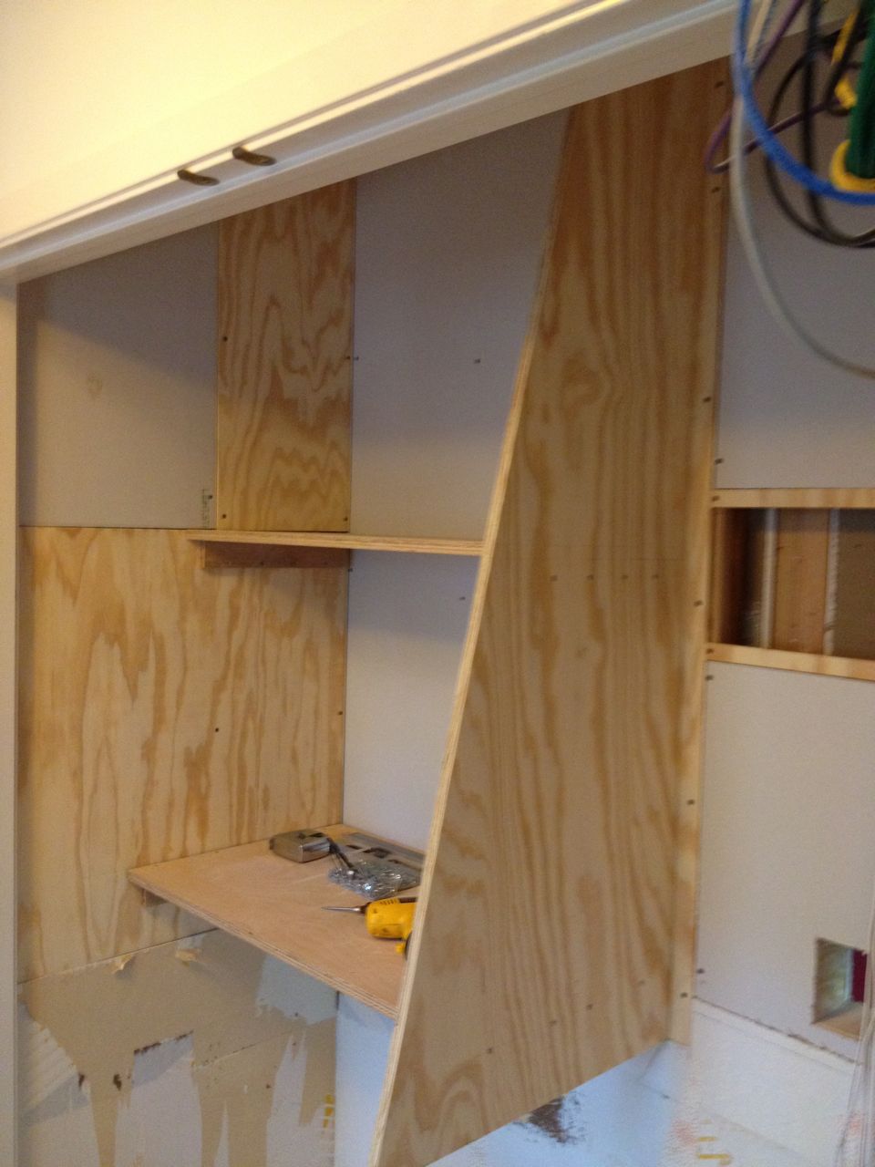
Both fixed shelves installed.
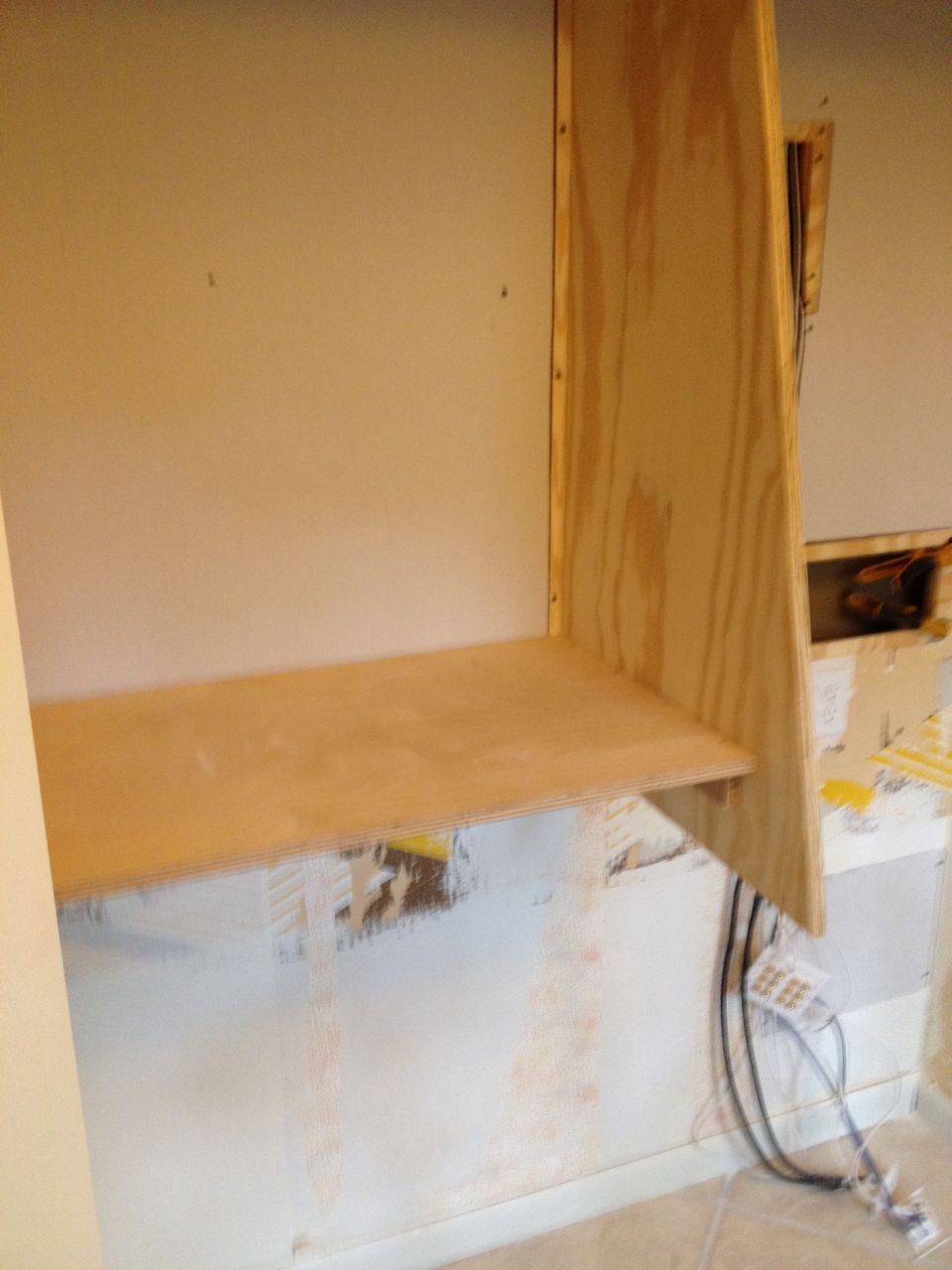
The first fixed shelf installed.
The original design for the left-hand side of the closet was for every
shelf to be adjustable. To address the center support issues of
straightness and stability, I decided to make one of the shelves fixed
to prevent side-to-side movement of the center support as well as
giving a straight anchoring edge to help anchor and flatten out the bow
in the wood. The hope was that adding this one fixed shelf would
straighten out the bow enough, and though it helped, I also had to add
another fixed shelf higher up to fully fix the problem. An important
lesson is to always use straight wood. I should have known better from
past experiences, but missed this somewhere along the line.
Sliding Shelves Installation
Sliding shelf offsets after installation.
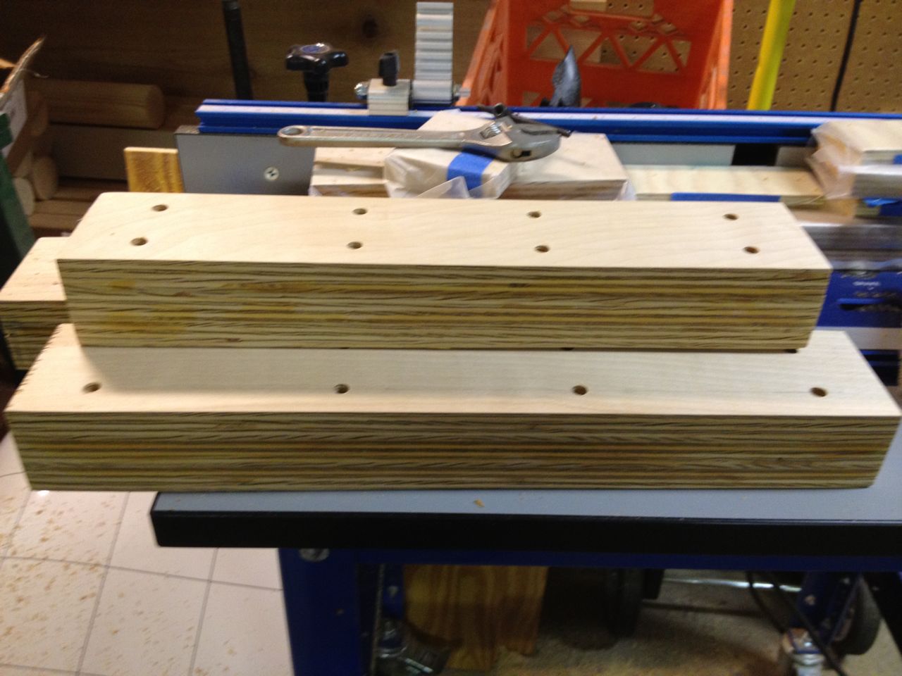
Sliding shelf offsets
With the center support now installed, semi-straight and fully stable,
I moved onto getting the true final dimensions I would need for the
sliding shelves. For the adjustable shelves, there is plenty of slack
to work with on the shelf widths, but the sliding shelves need to be
fairly exact. One mistake I made in my first design was to not account
for the fact that the door jamb of the closet is actually a couple
inches out from the wall. Thus, if you were to have a sliding shelf
flush with the wall (as my first design did), you would hit the door
jamb and not be able to slide the shelves further. I caught this in the
design phase though so knew I had to make some form of offset for these
shelves. I glued 3 pieces of 3/4" plywood to create a 2-1/4" offset,
which would be enough to clear the door jamb.

Closeup of installed sliding shelf and machanisms.
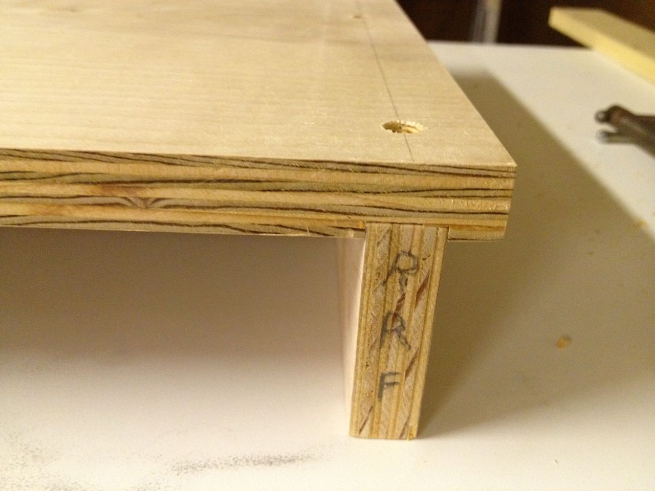
Sliding shelf close-up.
Trying to maximize shelf space and keep things clean looking, I had the
shelf surface overhang the sliding rail mechanism. The tolerances on
all this needed to be very close, no more than a sixteenth of an inch
off. However, there was still an unsolved problem: the wall and the
center support were not perfectly parallel and not perfectly flat.
This meant that the actual distances between the front and back of a
shelf were not the same and it also meant that not all shelves would be
the exact same width. Making each shelf custom to the actual
dimensions was not a big issue, but a width difference for the same
shelf between front and back was unacceptable. Despite the addition of
the fixed shelves, there was still a 3/16" discrepancy on individual
shelves, which was too much. Since I had an individual piece of wood
being used for the offsets, I decided that if I could taper the
offsets, then that would bring the center support and the offset
parallel. There was lots of measuring and re-measuring and some tricky
table saw cuts, but I managed to get a taper good enough to be usable.
Adjustable Shelf Installation
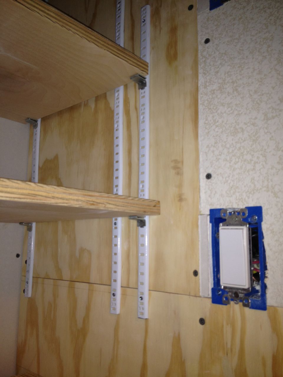
Close-up of adjustable shelf brackets.
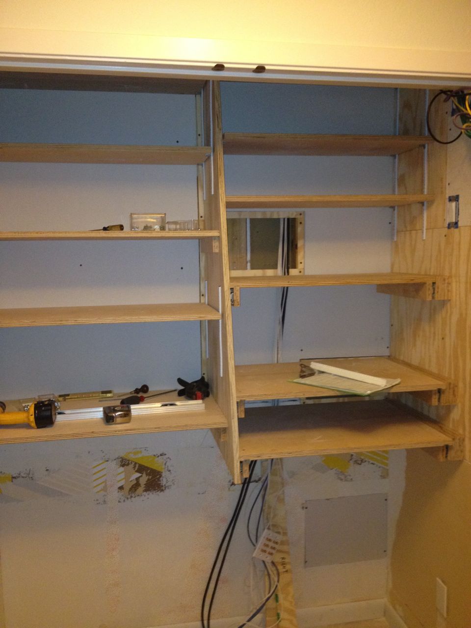
First view of all shelves installed.
The installation of the adjustable shelves was relatively
straightforward. Main keys are to ensure the brackets are level with
one another (and not the floor or ceiling) and that they are in good
positions so the shelves do not "tip". Because the shelves are of
varying widths, in some places, there was no single spacing of brackets
that would provide a stable shelf, so I used multiple brackets to allow
more flexibility in location and stability.
I had rough cut the shelves over a month before and allowed and extra
inch in both directions. Because of some surprises I found on the stud
locations, the center support was not exactly where I planned it to be,
but was slightly further to the right. Luckily, the left-hand six
shelves were still long enough, though not by much. I made the final
width cuts on all the adjustable shelves and installed them all to see
how they fit.
Network Re-routing
Remaining hole from old network cable access area.

Old network ceiling patch panel.
The day I was dreading had come: it was time to move all the network
cables from their current hard-to-access ceiling location to the new
wall access panel location. Why the trepidation?
- working in the corner of the closet ceiling is a pain;
- new A/C duct work we did made the wires and entry point hard to get to from the attic side;
- the wires had become a tangled mess and things were incrementally added over the years;
- I would have to be up in the (hot, itchy) attic for a few hours untangling cables: and
- I would be without Internet access until everything was moved.
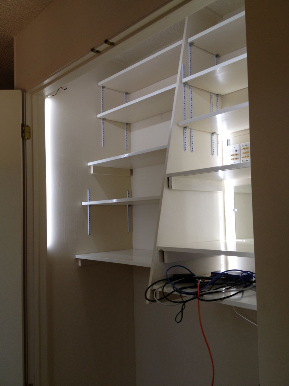
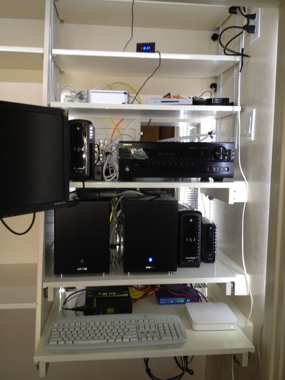
New temporary network setup.
Network cables successfully relocated.
It turned out to be better than I expected, but maybe mostly because I
expected a nightmare. It was for the most part uneventful, which I was
thankful for, and everything still worked after the move. However, with
all the cables moved downward, they no longer reached to the switch
mounted at the top of the door, so I had to do another reshuffling of
the network components. I wouldn't be able to hook everything up for
good until the very end.
Wallpaper Removal
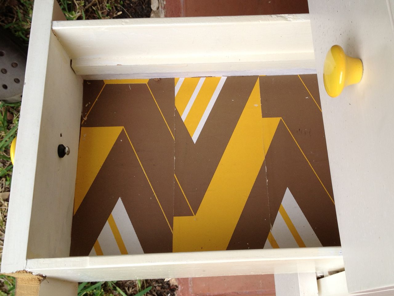
The older, hideous wallpaper (as also found in the bottom of the sewing desk drawers).
The old, not so nice wallpaper.
I did not remove the lower 3 feet or so of wallboard since that was not
needed for the shelves. But this wall did have two layers of wallpaper
on it that I wanted to remove before finishing the walls. The old
wallpaper was semi-ugly and came off relatively easily. The older
wallpaper below it though was hideous and was a known headache to
remove (from my wife's previous experience in the neighboring hallway.
The whole time I was underestimating the effort it would take to remove
the wallpaper, despite my wife's warnings. But when the day came to
remove it, I immediately regretted not simply removing all the
wallboard and replacing it with new board.

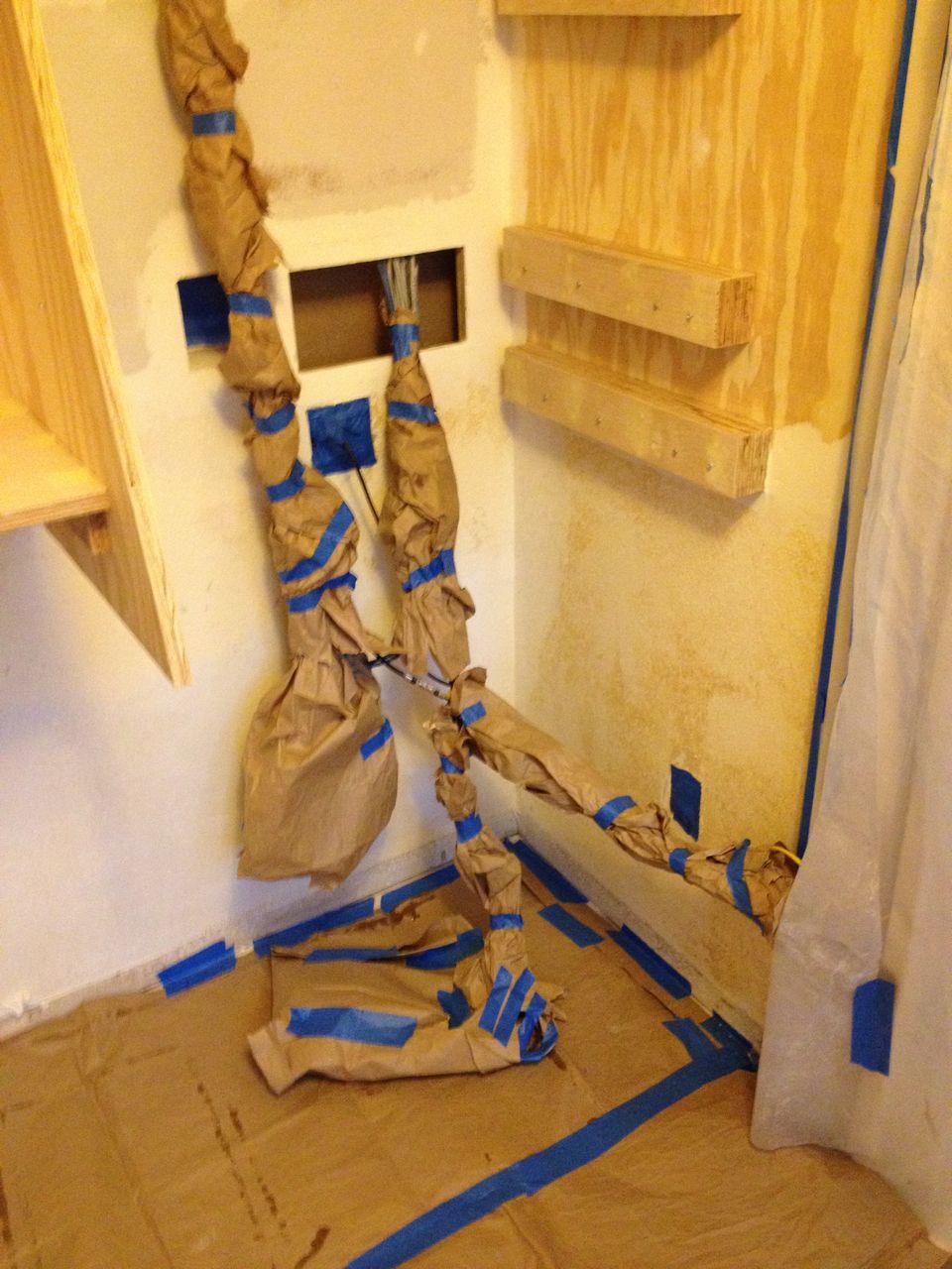
The wallpaper removal setup and mess.
Fortunately, I stumbled upon a trick that made the paper easy to
remove. I simply soaked the paper and waited. The plan was to then
try to use steam along with the addition water it had soaked up. After
waiting a few minutes, I found I could actually scrape the paper off
with my fingernail.
Spackling, Sanding and Painting

Sample of first pass at spackling.
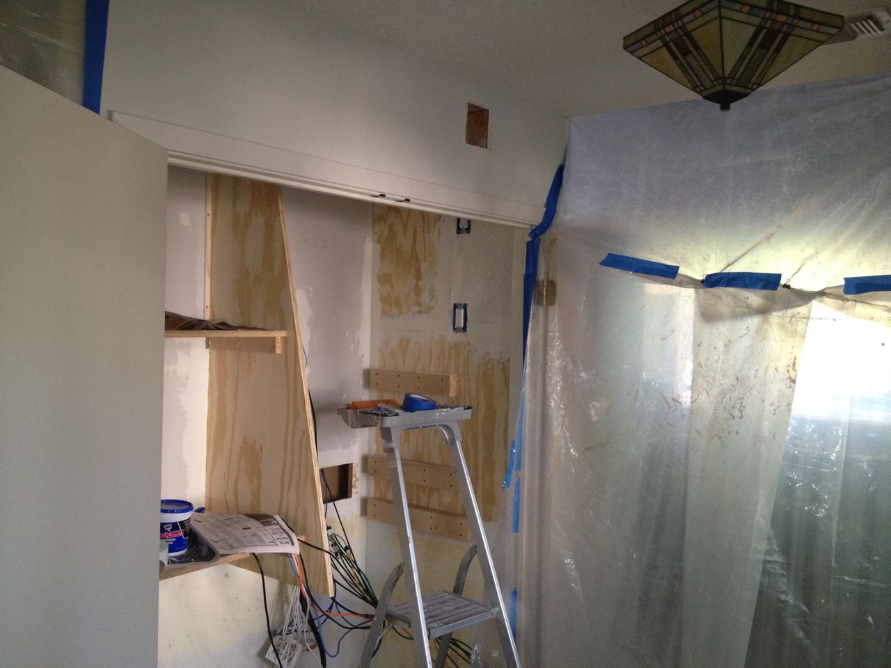
Plastic sheets to isolate closet area.
Spackling and sanding is always a mess, so we masked off the area as
best we could to minimize the dust. Naturally, the plywood and
wallboard were not exactly the same thickness, so my first pass at
spackling was not so great. After a day I took a second pass and
improved my technique enough to make a passable job of it. The
post-spackle sanding was pretty messy when using a power sander, so I
opted for hand sanding after a short while. I then masked the wires
and devices well in advance of painting. Why I did not do this before
spackling I do not know. I guess I think of masking as being just
before the painting, but it would have been handy to avoid all the
spackle and dust that accumulated during the prior steps.
Masking wires after spackling.
The painting plan consisted of 3 parts:
- primer coat of latex paint;
- second coat of latex paint;
- coat of oil-based, alkyd enamel to the shelf surfaces.
Lighting and Mirror Installation
Initial view of LED back-lighting.

Soldering set-up for working on lights and fan cables.
My plan for the lighting was tentative. I had bought a 16 foot roll of
LED strip lighting, some connectors and a power supply. You were
supposed to be able to cut the LED spool into sections and connect it
up in any way you wanted. I had never done this before so I was not
sure how it worked, or even if I had bought all the items I needed. It
was finally time to see if this would work for my lighting solution.
Since the parts I had were quite spartan, I needed to make some cables
to connect the power supply to the LED strips and to extend the reach
of the power supply. The crucial thing was planning the location of
the lights. I wanted both front and back lighting and I wanted it out
of the way. I settled on a ring around the inside door frame and a
couple strips along the back side of the area with the electronic
components.
Mirrors and back LED light strip.
And what good is the lighting if you cannot see the back
of the receiver or computers, which is where all the action is? I
installed a few 12"x12" mirror tiles on the back wall to allow easier
connections. I had previously resorted to a hand-hand mirror, but
these proved super useful later on when I got to connection all the
components back up.
I was pleased with the light locations and lighting level, but very
unhappy with the wire locations and the fact that I had "hard wired"
soldered connections. I would redoing the wiring a few days later to
make it easier to plug things in and out and the have the cabling
cleaner.
Fan Installation
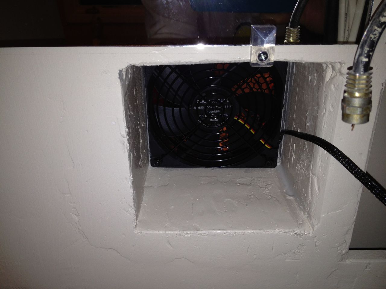
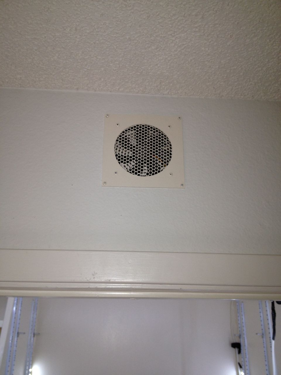
Inflow fan view from inside closet.
Inflow fan viewed from outside by kitchen desk
After some research, I had located this lice little two-fan package
with a temperature controller that was desired for home theater type
installations. It seemed the perfect solution as it had everything you
would need. Over the coming week I would find out the flaws with this
package. I fully expected to have to play around with the cooling
solution, but I was relatively confident that something with an inflow
and outflow fan would work and I settled on the common size of 120mm to
ensure that I was not constructing the closet around a proprietary
cooling solution.
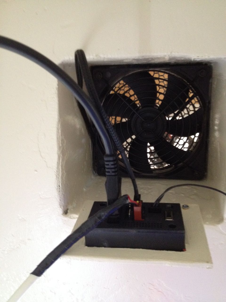
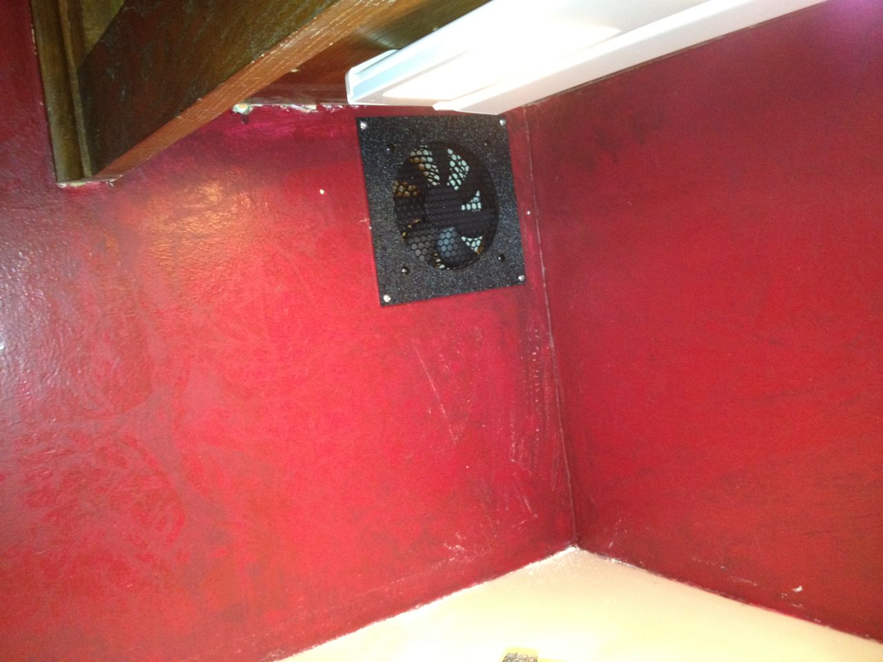
Outflow fan and controller viewed from inside closet.
Outflow fan viewed from outside, in front of the closet.
The inflow fan would be located lower on the back
closet wall, which meant it was drawing air from above a desk that
sits in the kitchen area. The outflow fan would be near the top of the
closet and vent out to the front.
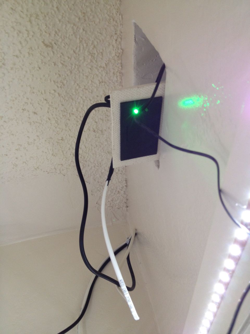
Another view of fan controller, this time with it on.
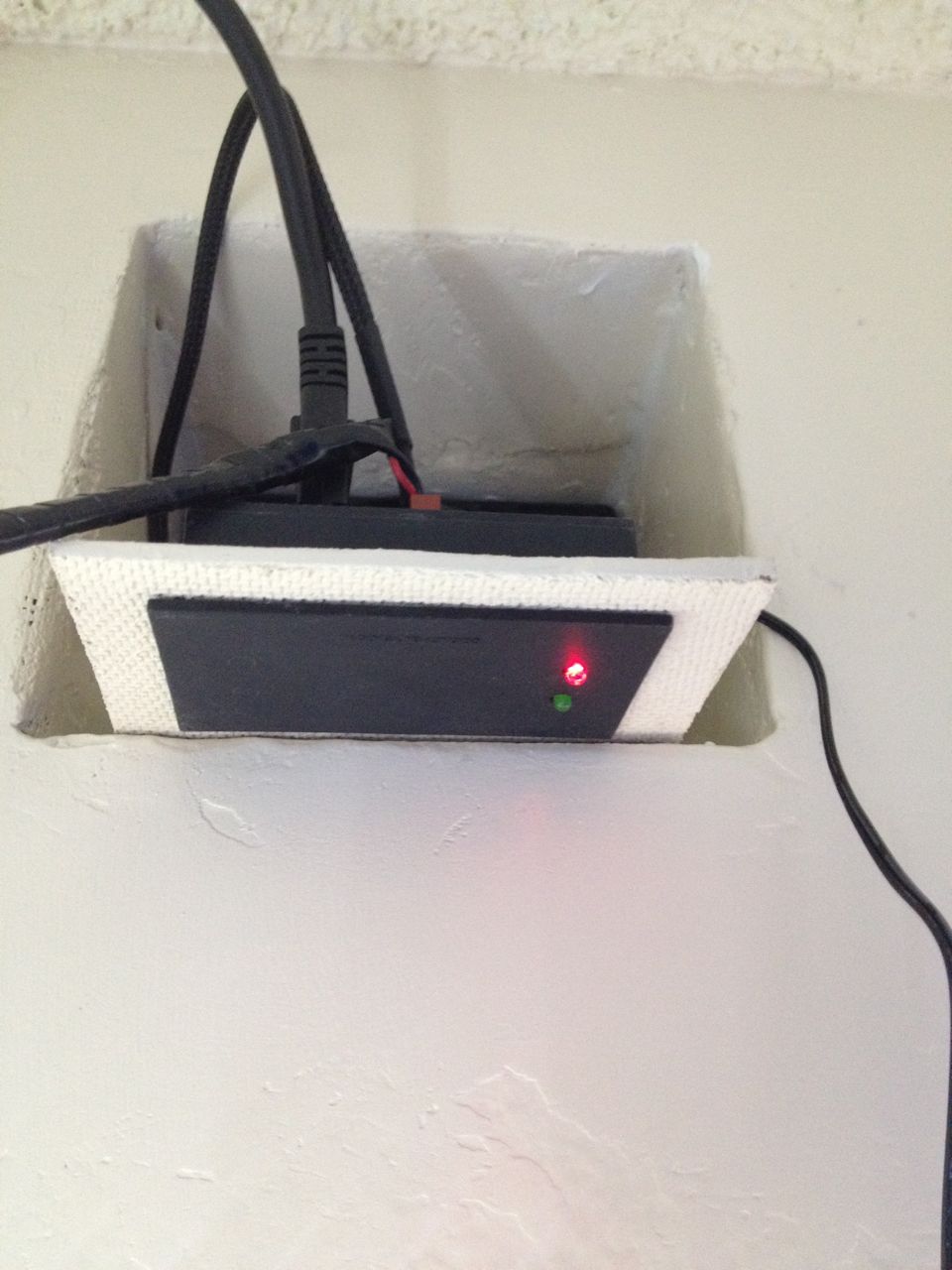
Fan controller mounted and in the off position.
The two-fan package comes with two fans, all the associate mounting brackets, power supply and two thermal controllers. The main problems with this package that I would have to fix were:
- Unless the two fans were right next to each other, the cable between at least one of the fans and the controller needed an extension. I had to custom make a 10 foot extender for the 3 pin fan connector from old computer parts. I wanted the fans to come on as pairs and not be tied to different controller, but to the same controller.
- The controller in the kit come preset to go on at 88 degrees and off at 81 degrees. I found this too inflexible. Even with the closet doors wide open, the temperate at the top of the closet does not go below 81 degrees. This meant that once the fans came on, they were not going off. Luckily, this company sold the exact same controller but where you could adjust the on/off settings. Why this is not part of that package I do not know unless they deliberately do this knowing you'll have to come back for more..
- The fans in the kit are quiet, but only about 40 CFM airflow with low static pressure. I would have to upgrade these to faster fans with 65 CFM.
Access Panels and Final Wiring
Back of network access panel.

Finished network access panel.
With the paint dry on the access panels, it was not time to attached the face-plates, hinges and latches and mount them.
Back of home theater access panel.

Finished home theater access panel.
I later changed my mind about where the cable TV and the antenna coax belonged. I originally had them as part of the home theater access panel, but later decided they were really part of the network. Reason for this is that we only have Internet so the cable only needs to go to the cable modem, and the antenna feed goes to the HDHomeRun box that converts it directly to a streaming feed over the network.
Putting it all Together
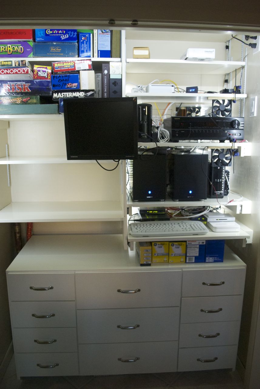
Shelving completed: left view.
Shelving completed: right view.
Shelving completed: front .view
The upper half of the closet was now ready to have the electronic
components moved into it. The cabinet drawers at this point had just
been painted and would require a week or so to dry before using (due to
using the alkyd oil-based paint).
Computer Install
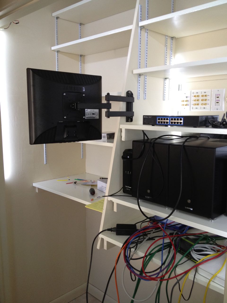
Computers Installed.
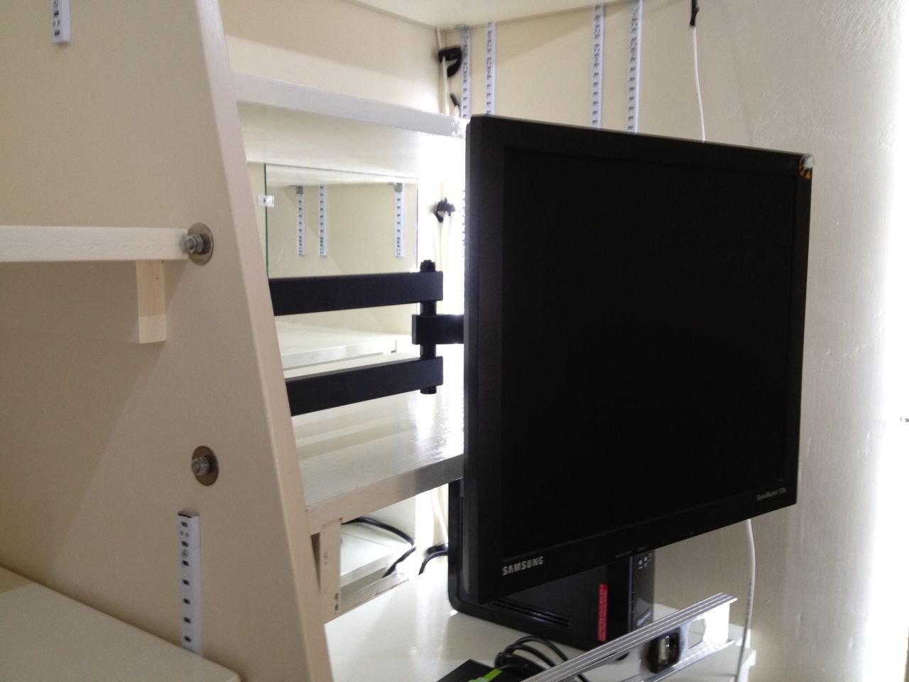
Move-able monitor arm installed.
First to move into their new home were the computers,
which included the last bit of hardware to be installed: the arm for
the computer monitor. There are two servers in here so I used an old
KVM switch and added an old, small LCD monitor I had laying around.
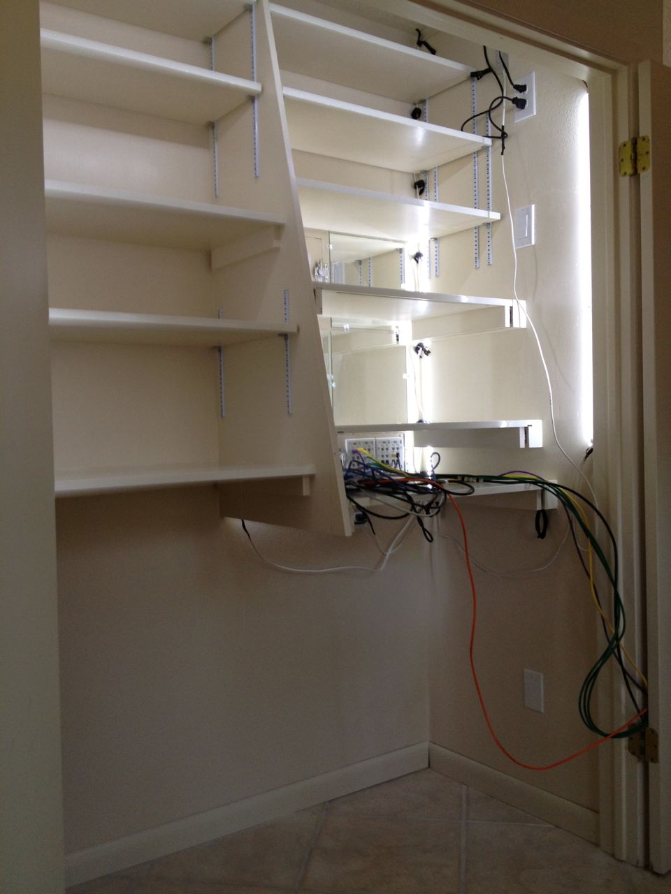
Network Set-up

Network wiring after some better planning.

Network wiring before any cable management.
I first connected all the network cables as they needed to be
logically connected. This brought home the cable management issue
which I knew was coming, but had no great plan for other than some
velcro cable ties. I had allocated 2 inches in the back for cables,
but with all the network cables I really needed a couple more inches
behind this one particular shelf.
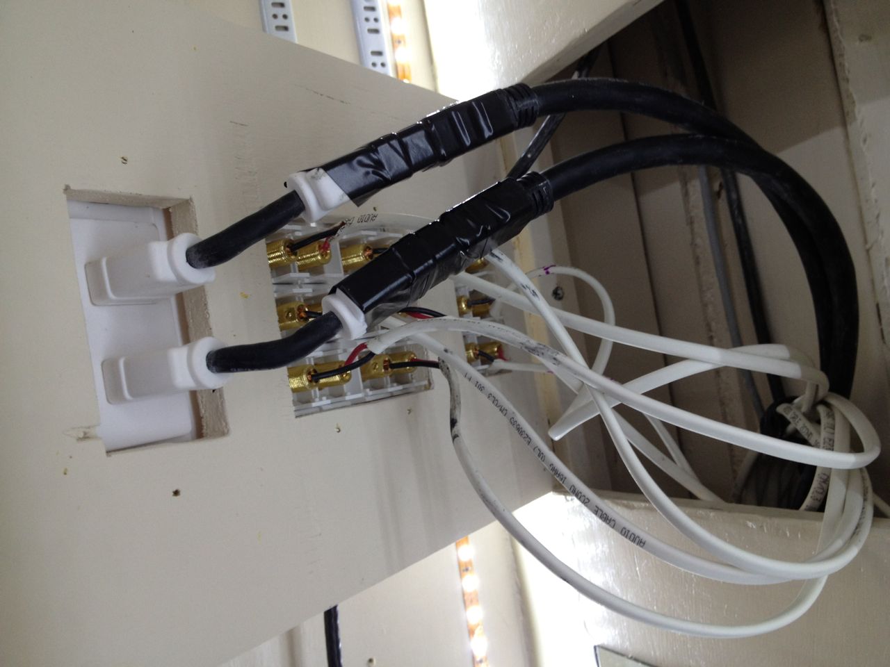
Home Theater Setup
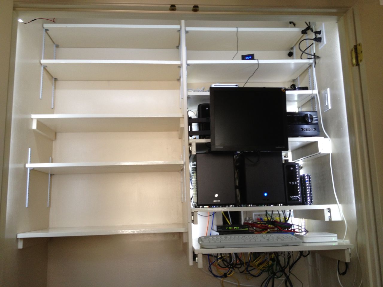
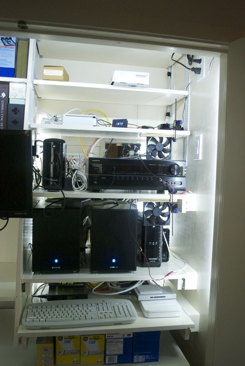
All electronics installed and wired.
After installing home theater components.
Next up was installing the home theater equipment and wiring it up. This
included the Infrared relay and flashers, the HDMI cables and all the
speaker cables.
New Light Wiring Harness
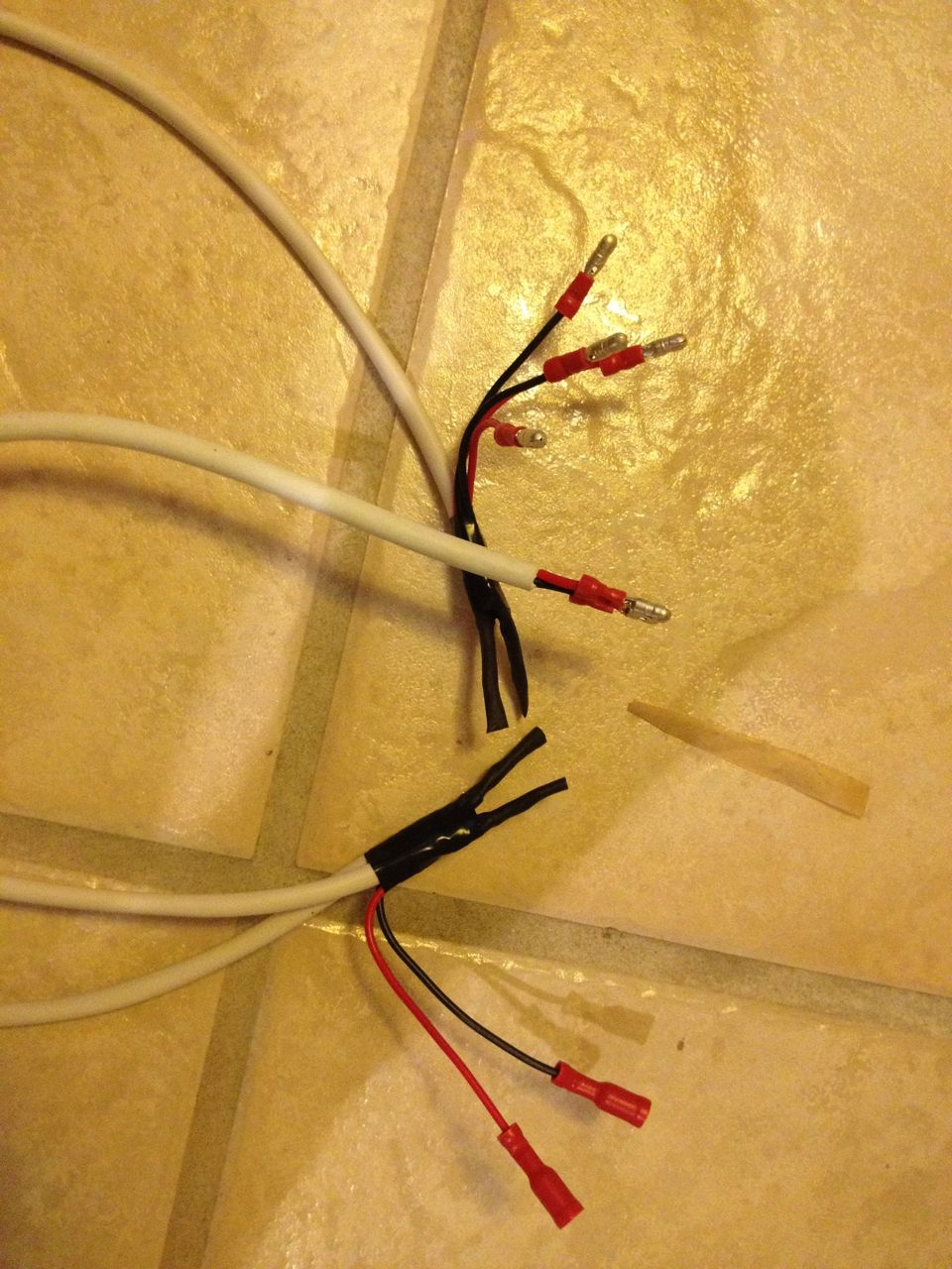
Close-up of wiring harness showing snap-in connectors.
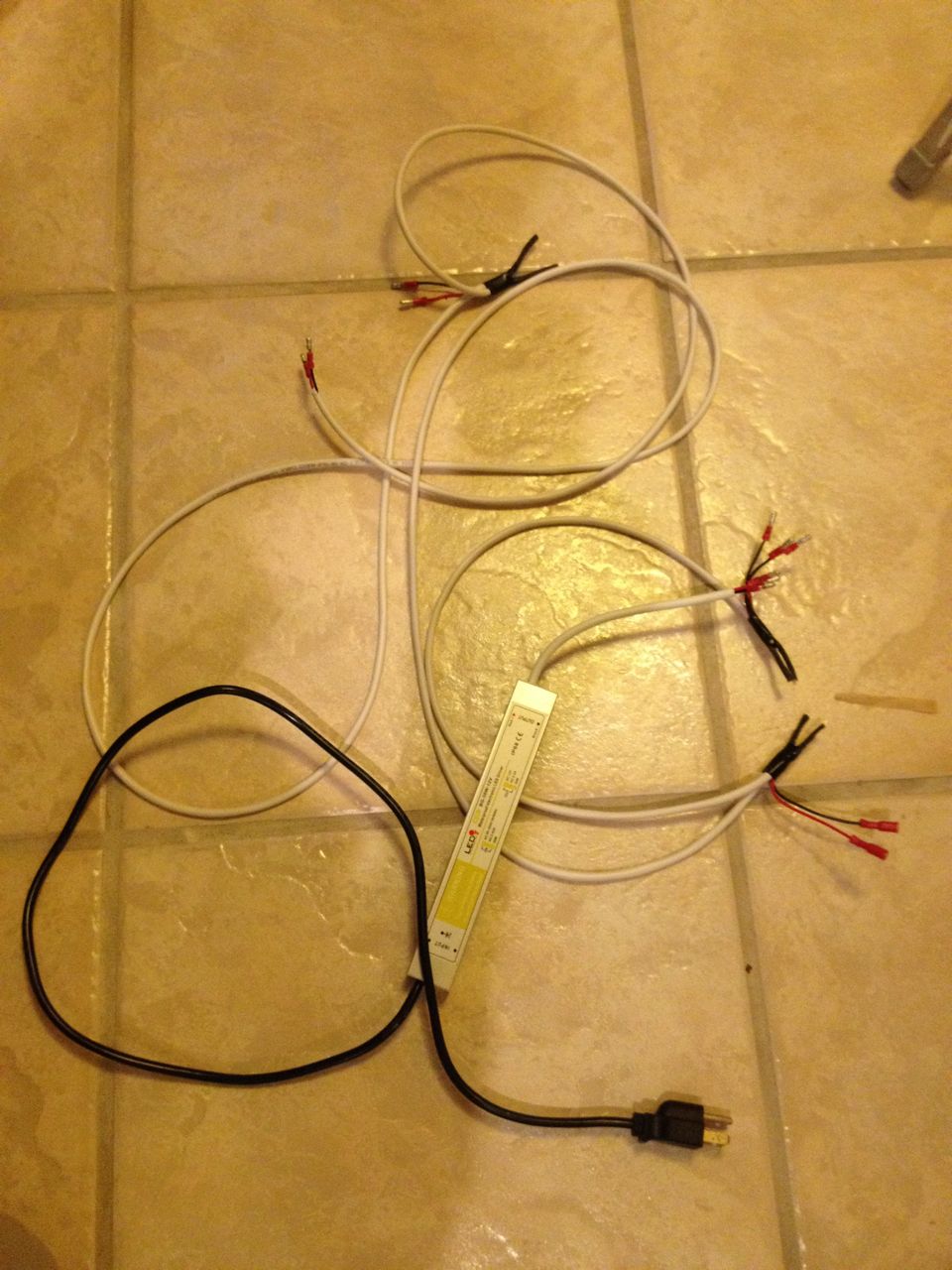
New wiring harness for LED lighting.
I had been waiting on getting some better cable for the wiring harness
for the LED lights. It came after everything else was assembled, so
that made it harder to install than when the closet was empty of all
shelves and equipment. I thought about waiting on populating the
closet until after rewiring the lights, but I felt that this would be
a good test on how easy or hard it was to run new cables in the closet.
It was harder, but not terrible and I did not need to move a lot of
things to re-wire the lights.
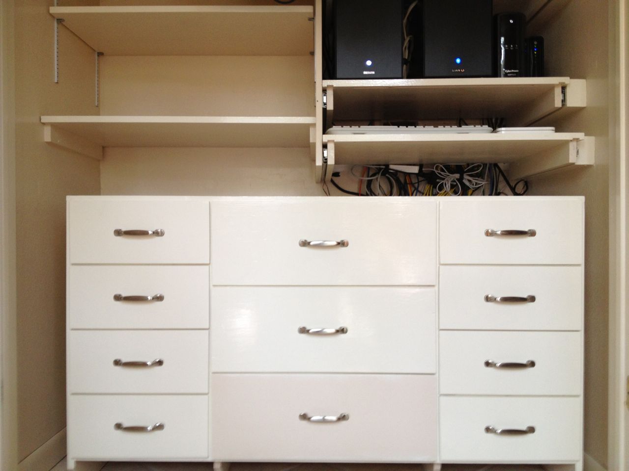
Cabinet Installation
Cabinet installed: left view.
Cabinet installed: right view.
Installing the cabinet and drawers was the last step. You can read more about the cabinet on the Closet Cabinet Project
Page. This was to be the finest moment: when the closet looked like I initially envisioned it...but there was a glitch.
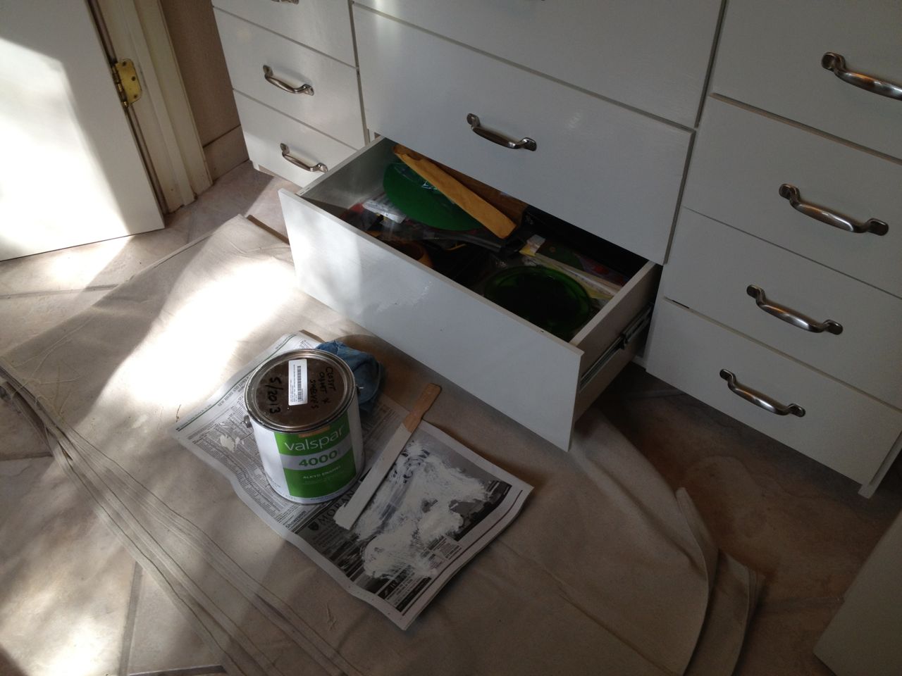
Fixing the mistake.
More obvious view of missed area.
I had forgotten to paint the front part of one of the drawers. I tried
to get the latex paint and the oil-based alkyd paint to match, but they
did not. In some sense this wound up being good because it was pretty
obvious to see that I had missed this area and it might not have been
if they matched better. I should have caught it earlier, but the
lighting in my garage (where they were painted) is not always great,
and some painting fatigue might have set in. Of all the things that
could have gone wrong in the final assemble of the cabinet, this was
very mild and easily correctable.
Project Completion
After allowing the cabinet paint to dry for a week, we put everything
back in the closet and had room to spare. Though we did get rid of a
few things, the main reason we have more space is before the shelves
and cabinet use the full depth of the closet, while the previous
shelves and desk where fairly shallow. Overall, I was pretty happy
with the result as it was very much like I initially envisioned it.
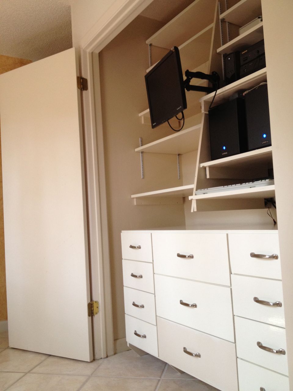
Finished closet with everything returned: left view.
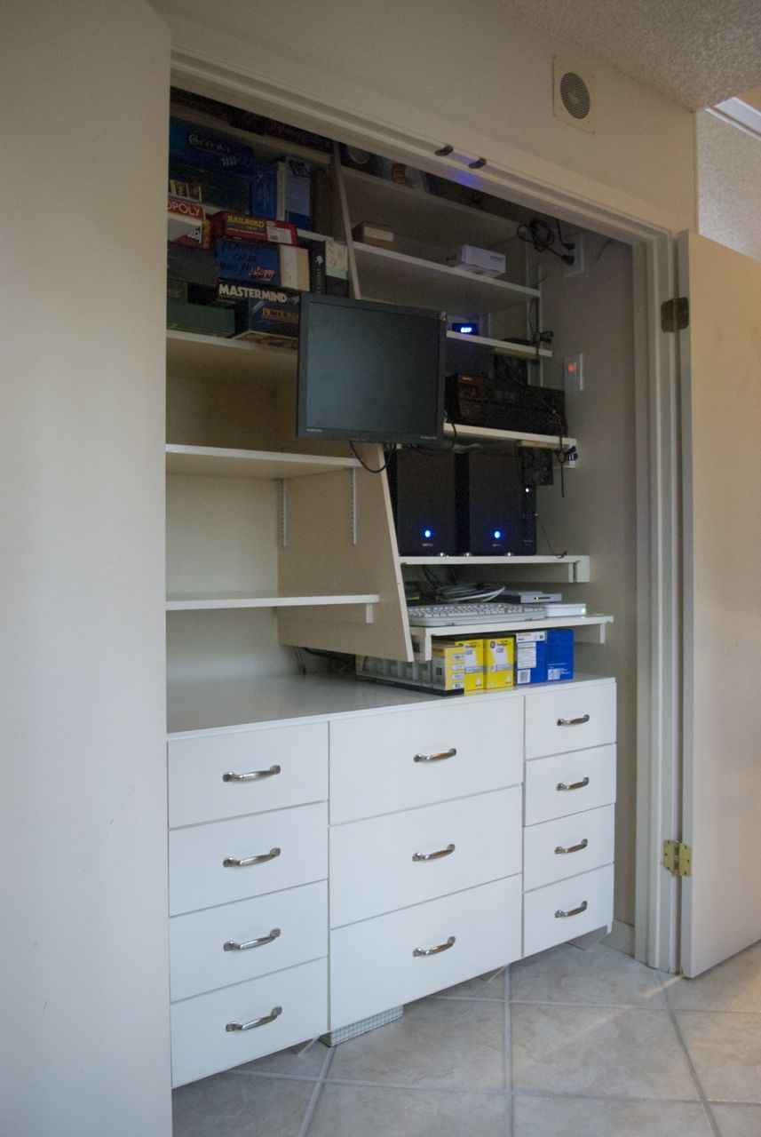
Finished closet with everything returned: right view.
Finished closet illuminated with lights.
Close-up of finished closet illuminated with lights.
Afterword
The small-ish fans worked alright, but they would struggle to just keep up when things in the closet were going full bore. After a few years, I tried to help the cooling situation with the Server Closet Door Vent Project.