 Cassandra.org
Summary
This project was a result of the New Decks
Project. You can read about the motivation and details on this web page, but an essential requirement
for the new decks was to have some nice, built-in lighting of some
sort. I decided I would do the work myself, since I did not want some
generic, off-the shelf solution. The generic off-the-shelf solutions
tend to be uninspiring, yet somehow expensive: you get a Walmart
solution for Neiman Marcus prices. I went with a 12V DC system using
LED lights since this would be both safer and more efficient.
Background
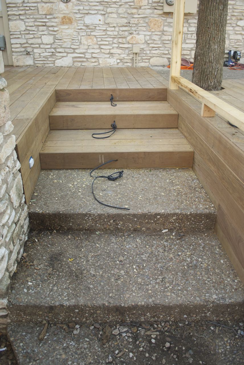
Wires on stair risers
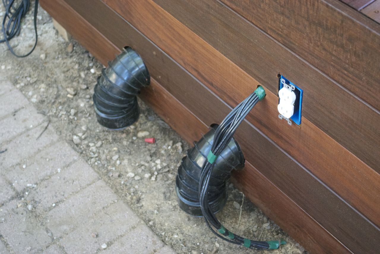
Low voltage wire terminus and outlet
I had spent quite some time researching deck lighting options, but
never had a firm idea as the deck construction got underway. I had
settled on a few things though:
- there would be lights of some sort on the stair risers;
- the lights would all be LEDs;
- the system would be low voltage, 12V DC, for safety; and
- there would be some form of permimeter lighting.
After the deck was finished, I had to get serious about making lighting
decisions. I had played around with LED strip lighting a few months
before as part of the Server and Storage
Closet Project and was generally happy with the result, including
the cost and flexibility. I decided I would use LED strip lights for
the perimeter lights, though I had to work out exactly where to put
them and how to affix them in a clean way.
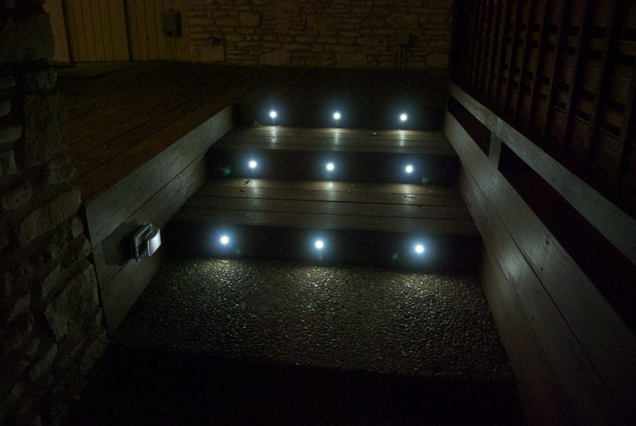
Stair Lighting
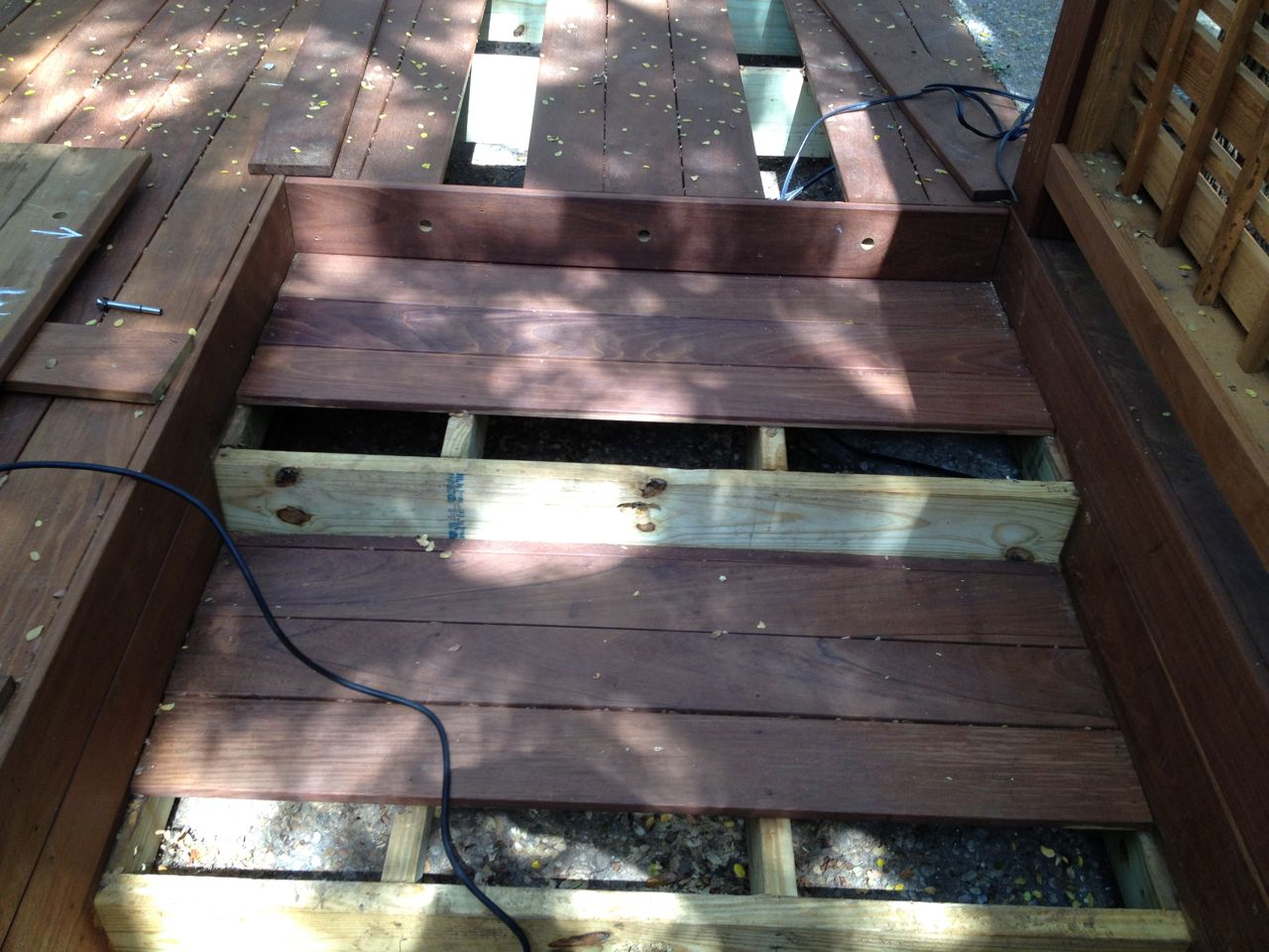
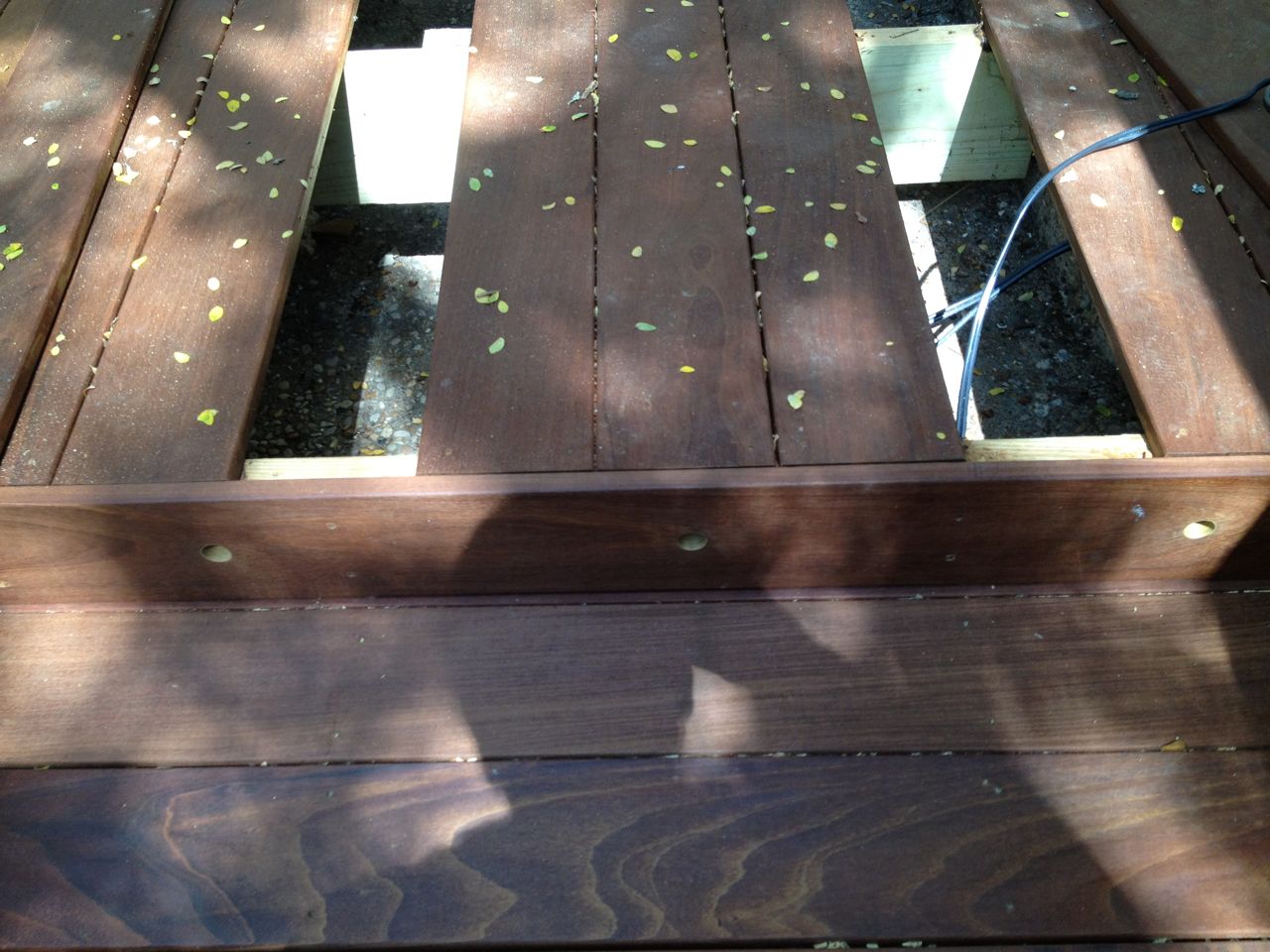
Dismantling for stair light install
Stair riser hole with wire removed
For the stair lights, I was very underwhelmed with the options for
stair riser LED lights. The best ones I liked were small round ones,
and they looked best if you had more than one per riser, which would
mean more cost and work. With 3 stair risers, this meant I would need
at least 6 of these lights, and for some reason, these were
ridiculously expensive at $30 a piece. These are tiny little LEDs in a
small weatherproof enclosure, so $200 total seemed too much to spend on
these. I eventually found a set of these that were $60, but you got 10
in the set. At $6 each, this was much more reasonable and within my
budget. It also mean I could put 3 on each riser, which I thought
would look better anyway.
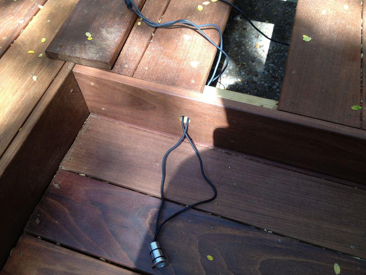
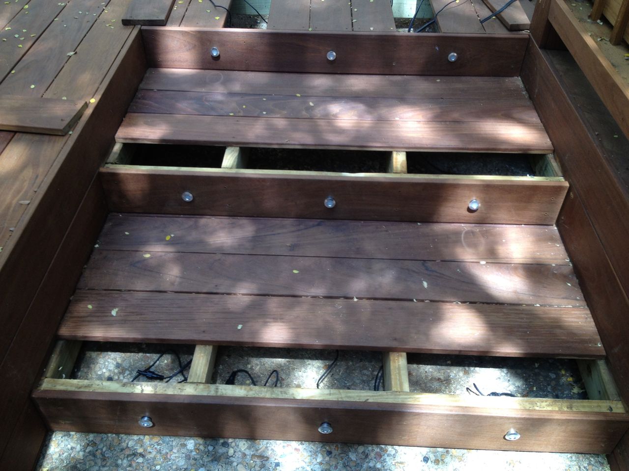
Stair light being wired
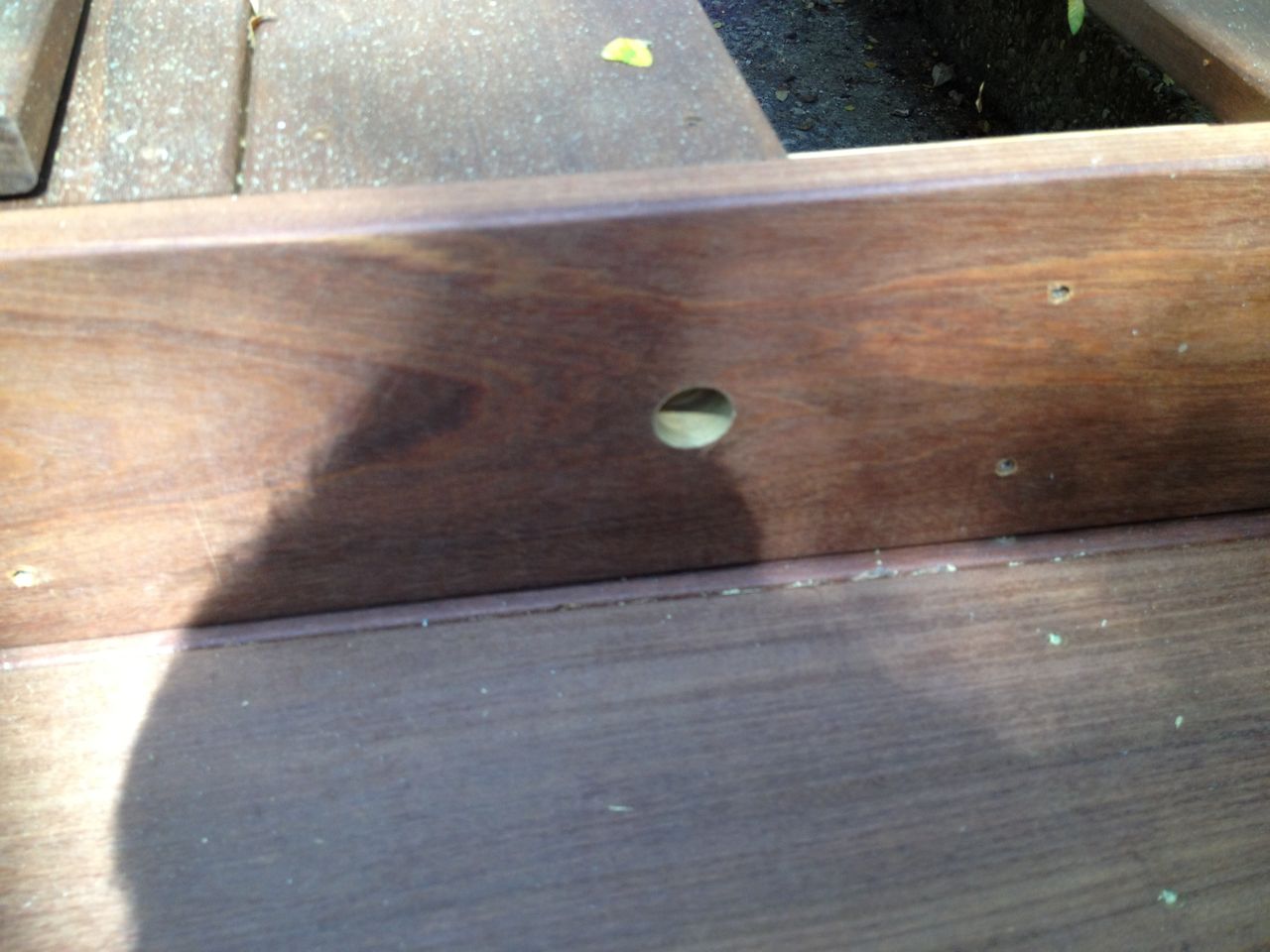
New holes for stair lights
I needed to dis-assemble some deck boards to be able to drill the holes
for these lights, as well as connect the wiring. The lights I bought
had very nice connectors to allow daisy-chaining them. Thus, instead of
having to have the low voltage wire run to each riser, I could just
daisy chain them from the first riser.
There was a little bit of annoyance in removing the deck boards due to
bent and over-torqued screws. The screw gun was definitely torqued too
high for this and the screws were driven deeper into the Ipe boards
than they should have been, which meant a healthy dose of splintering
when I tried to take them out. I also had to drill out one stripped
screw and throw away many bent ones as a result of the too much
installation driving torque.
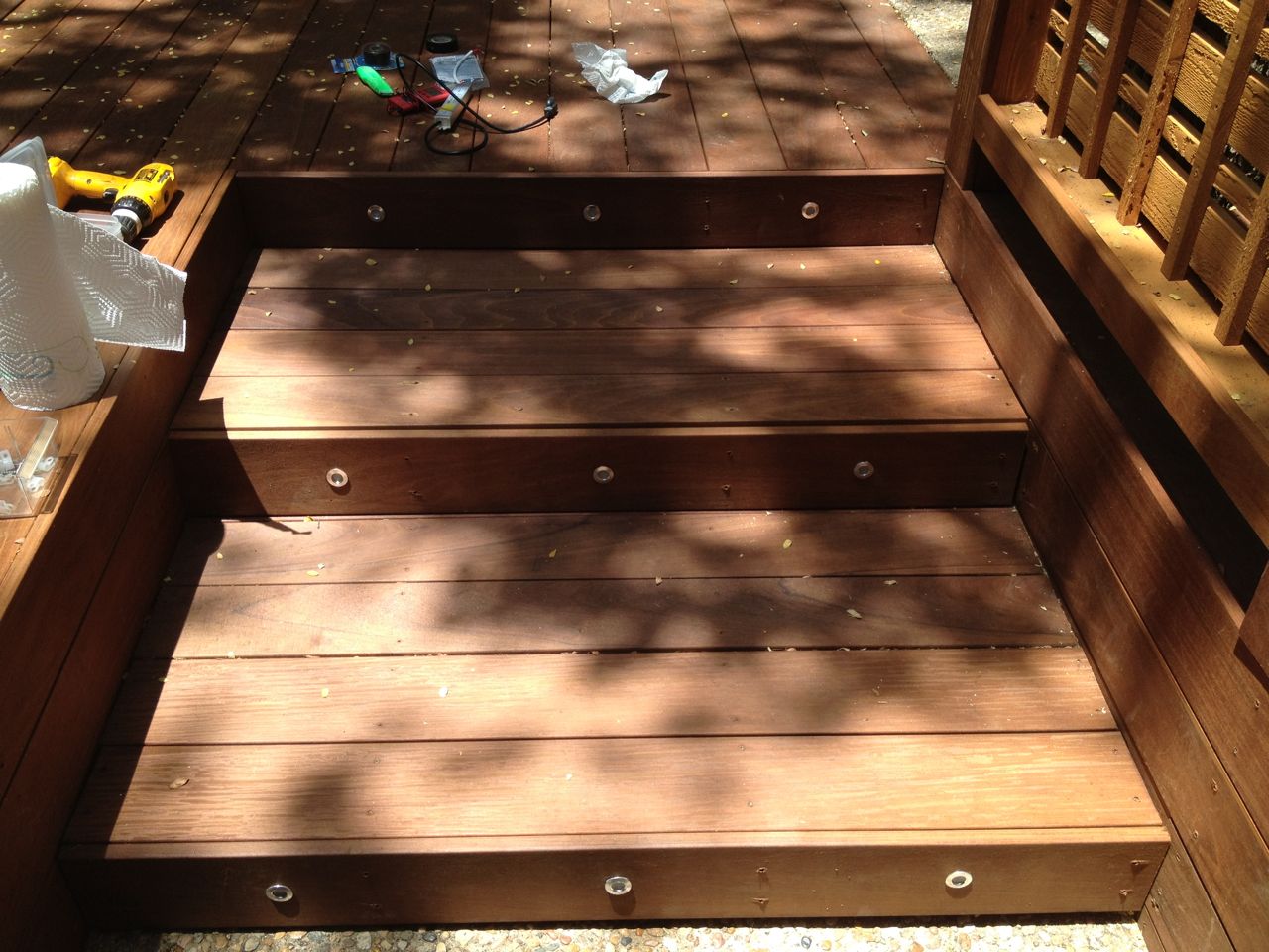
Final stair light result
Stair lights freshly installed
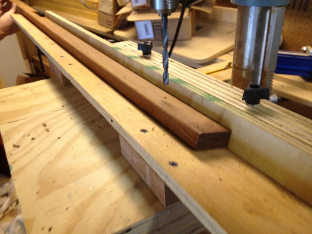
I needed to drill through the Ipe boards and the pressure treated
lumber behind it to accomodate the lights and their wires. I drilled
the Ipe holes first on a drill press using a Forsner bit (to get a nice
and clean hole), then aligned them on the stairs to mark where the
holes needed to be in the stair frame wood. I used a simple spade bit
in the pressure treated wood since this was going to be hidden behind
the deck boards with the clean hole. I did misaligned one of the boards
while doing this and I was left with a slightly annoying little gap.
This was not bad enough to spend the time to redo it, but enough to
annoy me every time I see it.
Though the lights and their connectors are weatherproof, I used some
clear silicone sealant around the front to add a little better to the
seal and act a bit as a glue to hold them in place. The lights had two
O-rings on them, but the holes were not that precise for that to be
much help in holding them in place.
Wiring and Control
One of the most important things for me in the deck lighting was to be
able to conveniently turn it on and off. This meant a switch in some
convenient location, which meant nears one of the doors from the house
(co-uld be inside or outside). As the overall complexity of the
project came to life, it had a reality in terms of costs, time, budget
and coordination, so this "convenient switch" requirement got lost in
the shuffle. I would think about it occasionally, but did not want to
complicate the project any more than it already was. I figured I might
be able to figure something out later.
The working plan that evolved during construction was to have a
transformer on the back side of the deck, plugged into a new outlet
there, and where all the low voltage wiring ran to. A transformer in
this location would not be convenient for turning the lights on and
off. All along, I ideally wanted a switch in the house, but that would
require a lot of electrian work and labor costs. It turns out that I
had a fortunate alignment of circumstances that led me to a beautiful
solution:
- an unused switch in the hallway going to the side deck;
- convenient access to the attic of one of the deck's low voltage wires;
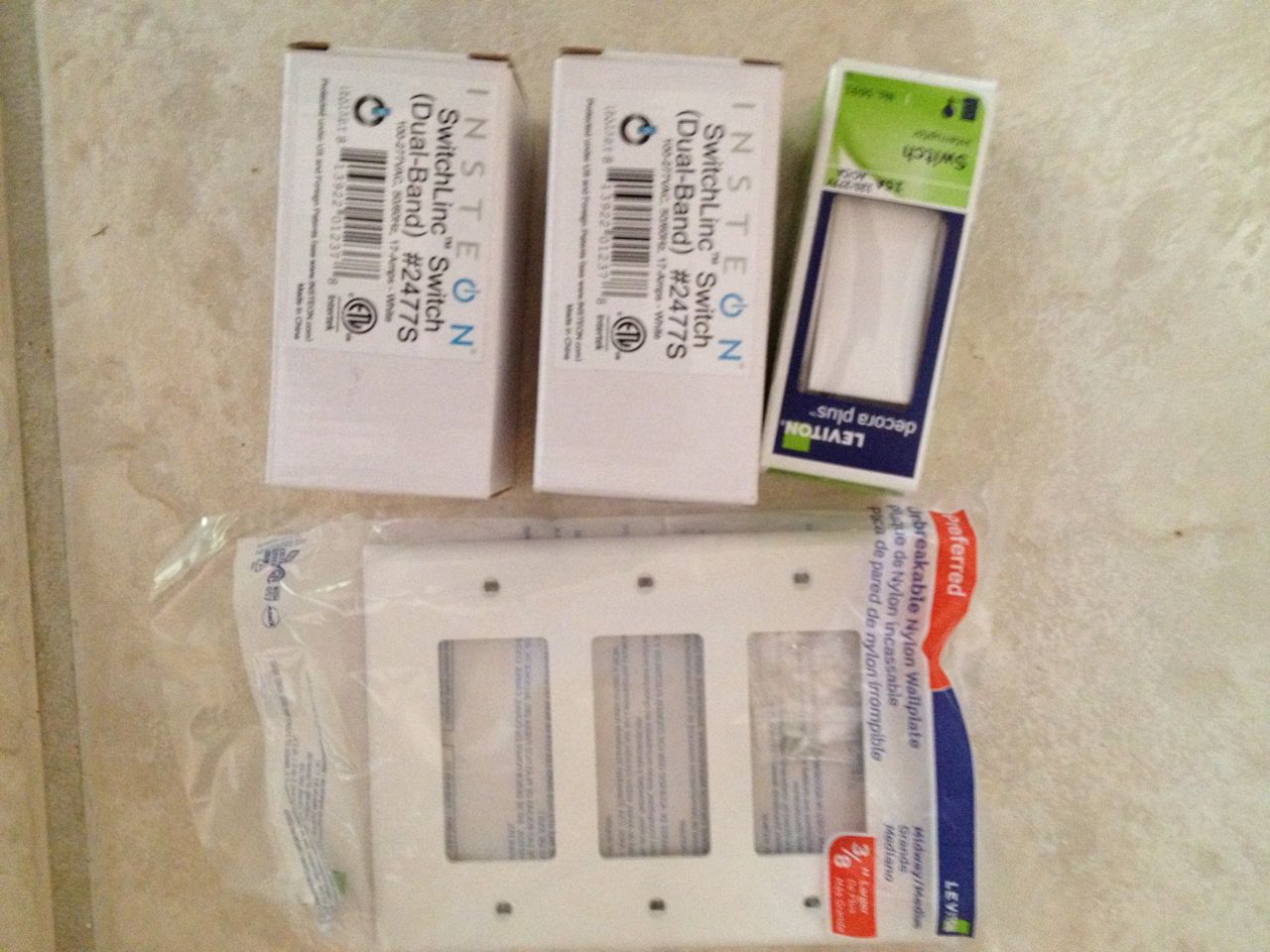
Parts for redoing light switch
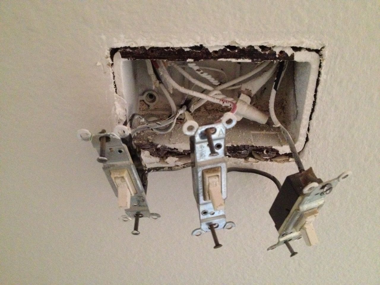
Old light switches
The unused "mystery" switch was a switch I had never figured out in all
the years I had lived in the house. This project caused me to tackle
this 14 year old mystery. After tracing wires, it turned out that the
light in our utility closet was a combination light and fan and each
was on controlled by a separate switch. The fan must have gone bad
before we ever moved in, so I never knew it even existed as part of the
light fixture.
After all the other deck lighting work was completed, I also replaced
the old switches in the hallway. Reasons for this were:
- I wanted a controllable (Insteon) switch for the deck lights;
- I wanted a controllable (Insteon) switch for the overhead spotlights;
- I wanted to make the utility closet switch match the Insteon switched (decorator-style); and
- I wanted to re-arrange the order of the switches to make them logically match their physical locations.
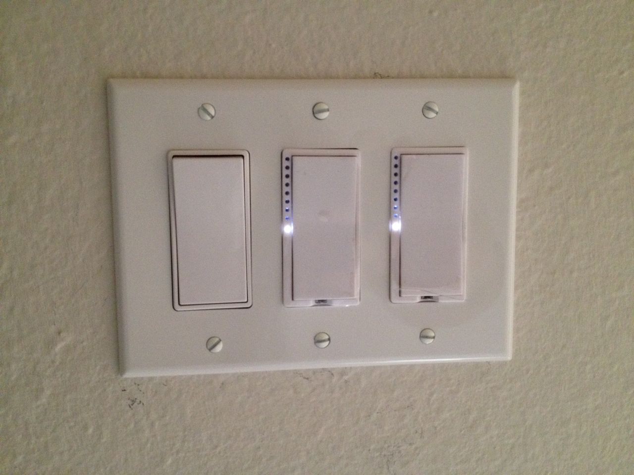
New switch panel completed
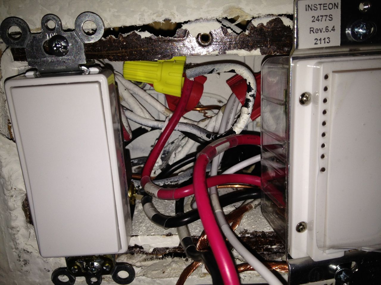
Cramped wiring for new switches
The Insteon (controllable) switches have a feature that is both good
and bad. Unlike a regular light switch where you run the sire directly
into the switch, the Insteon switches have wires already running out of
them and require you to wire-nut them to the main electrical wires.
This makes them slightly easier to wire, but it also causes the o-utlet
box to be very crammed since each wire nut has to be acommodated and
they are not small.
Note that for switch controlling the overhead light that was already on
the side of my house by the decks, I replaced the existing, decrepit,
bulky dual spot light with a new, sleak LED version. This provides a
brighter light than the deck lights will, which mmight only be useful
if I needed to do some work outside at nighttime. Otherwise, the deck
lights are ample lighting for the common usage patterns we have.
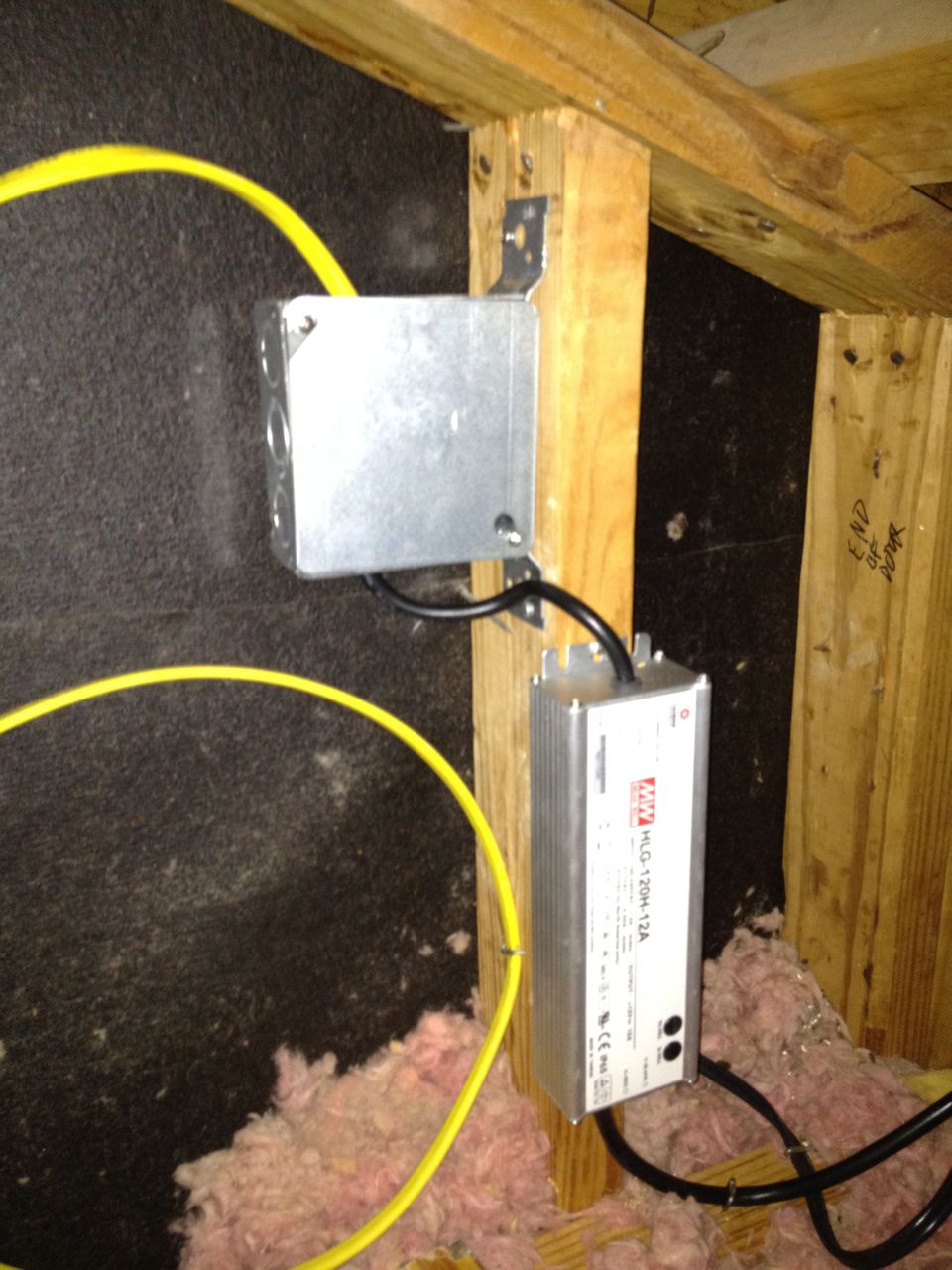
DC driver and junction box in attic
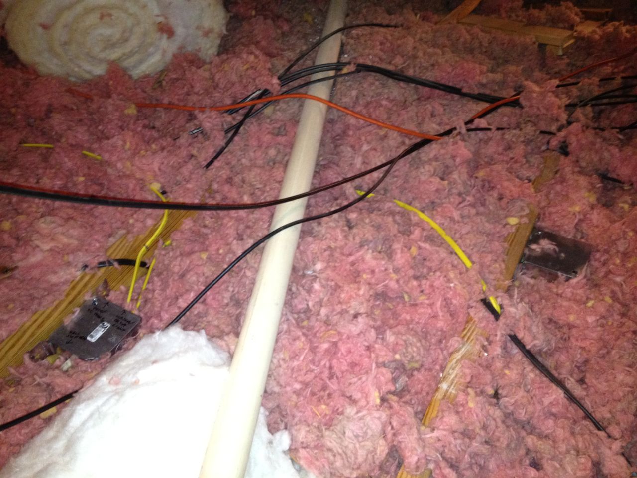
New junction boxes to re-route to DC driver
I had the switch, but this was controlling 120V AC power, while I
needed 12V DC power to the deck lights. I did not want to run new 120V
AC electrical wires outside due to the cost, complexity and disruption
is would incur. Running a few extra wires and junction boxes in my
attic was easy. The low voltage line in one corner of the southeast
deck is right against the side of my house, and the general contractor
nicely had left ample slack: enough to run up the wall and into my
attic. This meant I would have to put the AC to DC
converted in my attic, and use that low voltage wire as the main feed
to the rest of the wires.
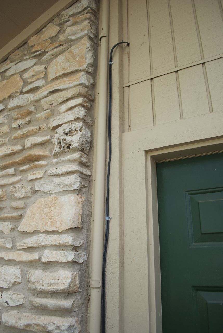
Low voltage wire exiting attic
Finding the right AC to DC converter (a.k.a., DC driver) was complicated:
Generally, sites like Amazon did not have enough details for me to know
exactly what I was getting, and specialty places seemed to be seriously
overcharging for these. What I did was find a high-end LED lighting
site, zoomed in to find the brand name of the transformer and then went
looking for this brand at a better price. I bought it from mouser.com which was a site I had previously bought
electronics from and it was fantastic in having all the specs and
manually so I knew exactly what I was getting.
- there are both 12V DC and 12V AC lighting systems out there, and some sites did not specify whether the transformer was AC ro DC;
- I struggled with what wattage to get to ensure current and future needs (Isettled on 120W); and
- I wanted to make sure I got a high-quality one since it would be invisible to me while mounted in my attic.
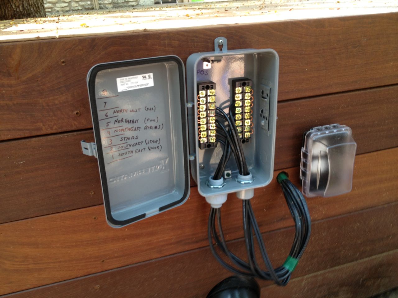
Mounted and wired junction box
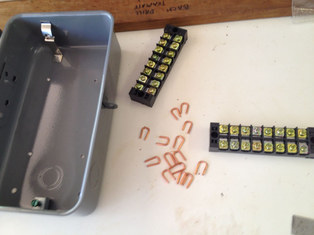
Terminals, jumpers and empty box
Since all the low voltage lines terminated at the same place (back of
the deck), I just needed to splice them all together there. One of
these wires would be the feed from the attic transformer, while the
rest would run to the wires in each corner (and stairs). Thus, the
original plan of locating the transformer on the back side of the deck
was obsolete, but I did need some "clean" solutionn to splicing them
all and a weatherproof way to keep it all dry.
I had recently been in Fry's looking for connector ideas for the LED
strip lights for the Server and Storage
Closet Project and noticed terminal blocks. Something triggered
this memory, and these seemed like the ideal way to cleanly splice the
6 12 gauge wires together. I wound up getting these terminal block
through Amazon though. I needed to make little jumper wires to tie all
the wires in these blocks, and that wound up being relatively simple
using some 12 gauge, solid electrical wire from scraps.
I looked in the local home improvement store for an wetherproof
enclosure, but they had nothinbg suitable. I have a box for my pool
pump timer/controller and wanted something like that, only smaller and
that would allow me to easily mount the terminal blacks. I eventually
found the right thing on Amazon, though it took some digging to turn
this up.
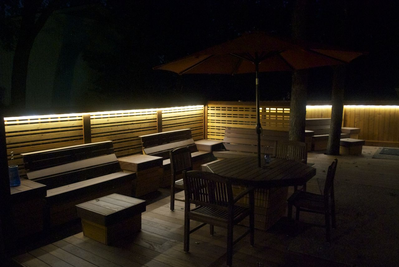
Deck Perimeter Lighting
After considering post lights and rail lights, we settled on using a
strip of LEDs around the underside of deck screen and fence. Since
these would be near eye level, you want to avoid direct line of sight
to them them since that would be too harsh. Mounting them facing down
was the answer. For the southeast deck, the new front-facing fence
had 2x4 cross members at a good height and this would give me 1-1/2" of
space to work with to mount an LED strip to the underneath. There were
these nice silicone brackets that needed about 1 inch to mount.
Drilling mounting holes in rail
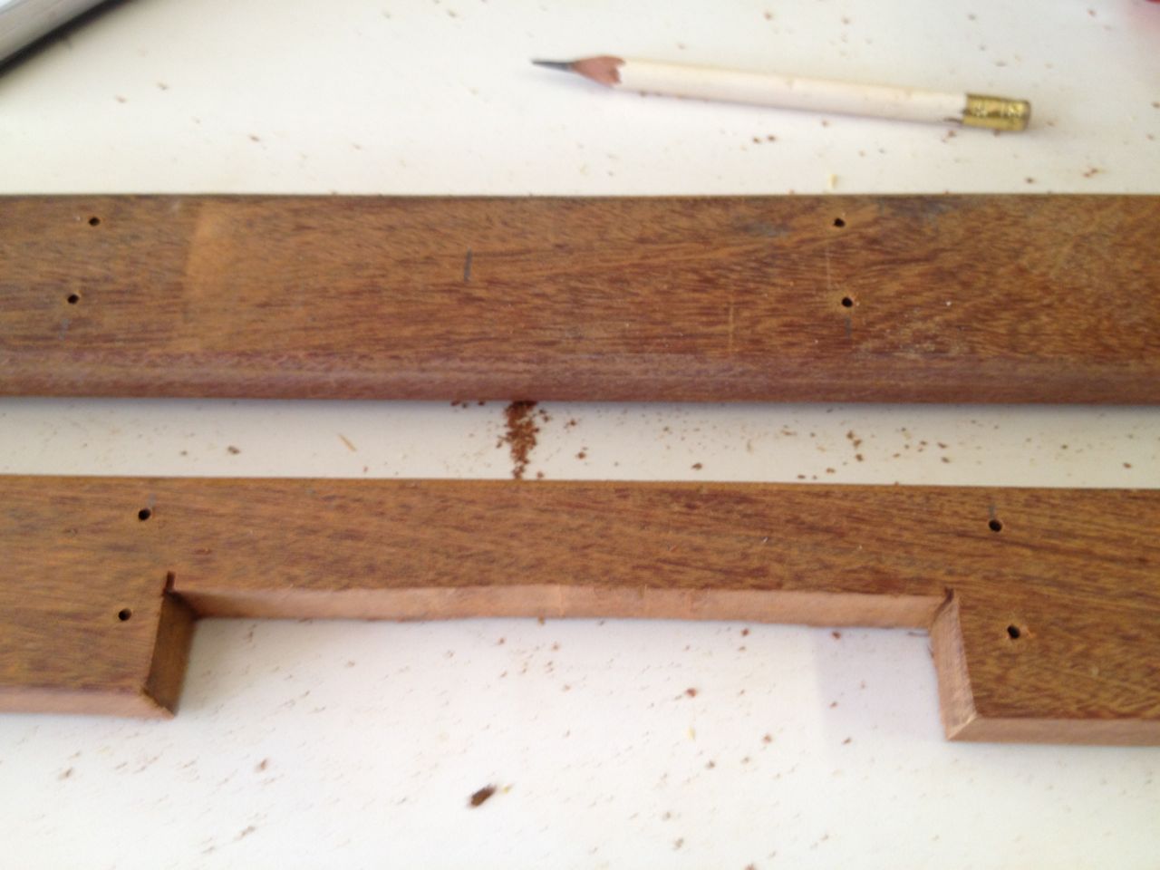
Notch in LED mounting rail
Mounting the LED strip along the Deck Screen Page of the
northeast deck was a bigger problem. The only mounting surface was
only 3/4" wide, so not enough to use the nice brackets. I eventually
stumbled upon sites that sold LED light "channels", complete with
translucent covers. These would be thin enough to mount on the deck
screen. The problem with this solution was the price. The cheapest
ones I found were about $25 each and that was just a 1 meter segment. I
had 5 meters of LED lights to mount. Further, for some inexplicable
reason, these do not have any mounting holes, so I would have to do
work to drill them and seal them.
I eventually decided that I could get a wider mounting area by adding a
strip of wood to the underside area and then mount the LED strips to
that. This also had the nice effect of offsetting the LED strip so
that I would not need to splice it around the two posts that would have
otherwise been in the way.
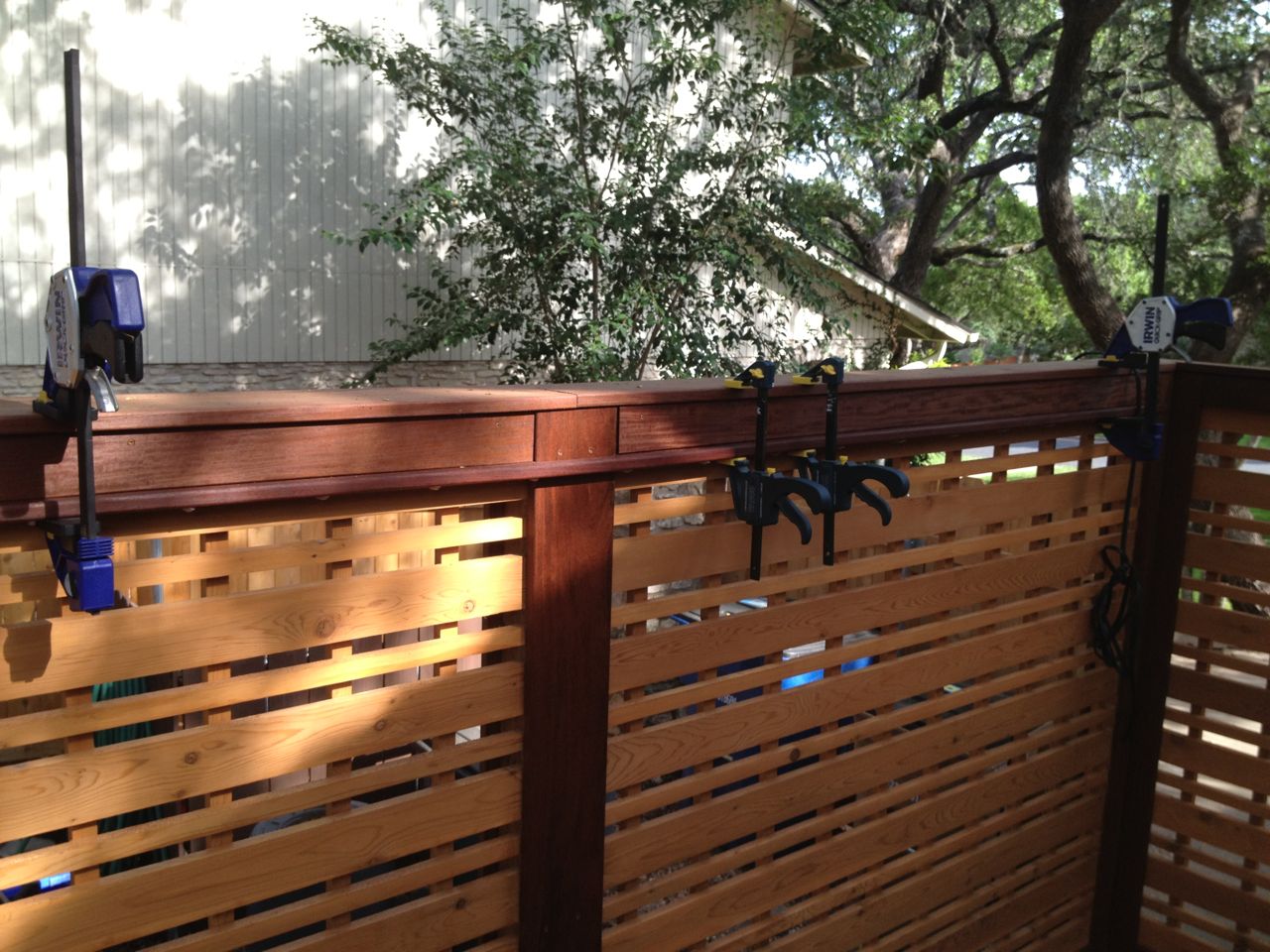
Installing LED mounting rails
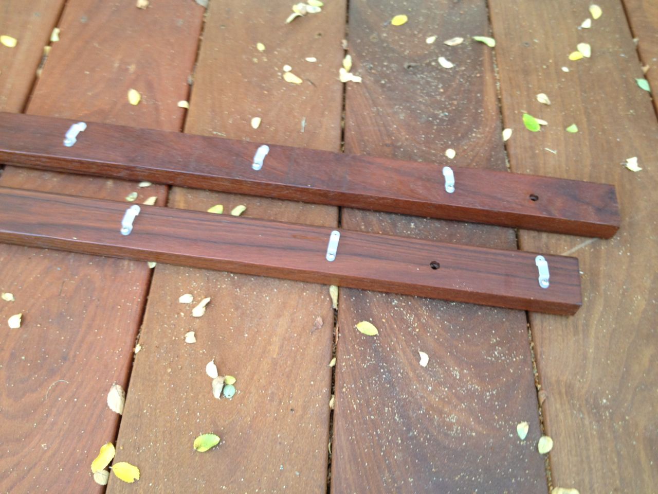
Mounting rails and silicone brackets
The down side here is that I had to use an 8 foot long 1x4 board of Ipe
that was allocated to the upcoming Deck Table (see Deck Furniture Phase II
Project Page). I ripped this exactly in half which gave me about a
1-5/8" surface to mount the LEDs on. I would space the silicone
mounting brackets every 6 inches to give it a "sag-less" look. I
needed a lot of very small stainless steel screws and after striking
out at the local home stores, I discovered AmazonSupply.com, which was truly great
discovery.
I drilled all the small silicone bracket holes before mounting as this
was easy. I also needed to ensure the holes for mounting the rail
itself were on a slight angle. There would be no room up against the
deck screen to get my screw gun close enough for driving a screw
straight in. This made the location of these mounting holes important
to get right.
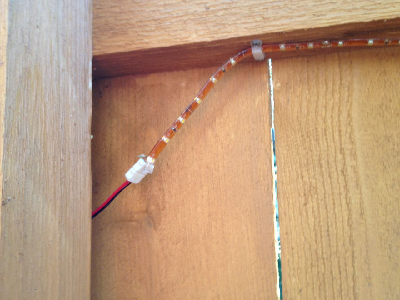
Closeup of (unsealed) inter-strip connector
LED strip on southeast deck fence
For the southeast deck, where the LEDs would simply mount to the
underside of the fences 2x4s, the complication here was that I would
have to cut the LED strip into 3 segments. The fence is shaped to be 3
sections and you cannot bend an LED strip in the horizontal direction.
They make special, nice connectors to make splicing them easy, but the
problem here is that I would be splicing LED strips that were
weatherproof and these connectors were clearly not weatherproof. I was
not able to find these splicing connectors in any weatherproof form,
plus you have to peal back some of the silicone weathproofing from the
LED strip to use the connector. Thus, I needed to find a way to
weatherproof these connectors and the splice points.

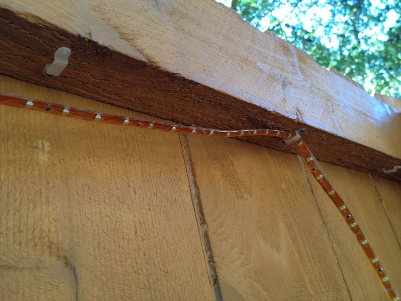
Final LED strip splice
LED strip and low voltage wire splice
I found this
silicone tape that looks a bit like electrical tape that was
supposed to do what I needed. It might do the job, but it will be
helped by the fact that I was able to tuck these splices under the 2x4
so they will be mostly shielded from the worst of the weather. I also
added a wrapping of electrical tape over them for more mechanical
support. The result is not very pretty, but will do for a while. I
expect I'll need to redo these in not too many years and maybe will
have a cleaner solution by then.
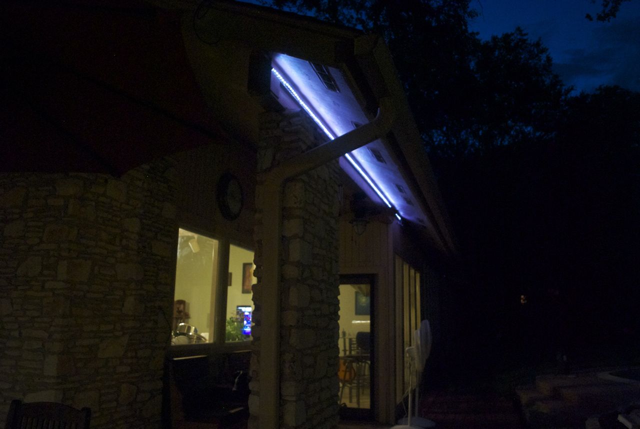
Northwest Deck Lighting
The LED strips installed around the decks were monochrome (warm white),
but I had originally hoped they would be fancier multi-colored LED
strips. This is not Christmas tree multi-colored, but the ability to
set the LED strip to be any color you like (the entire 16 million
colors of the RGB space). Early onwards, in my LED experimentation
phase I bought this Color Changing LED
Stip Kit. At $34, it was a great bargain and worth buying to
experiment with.

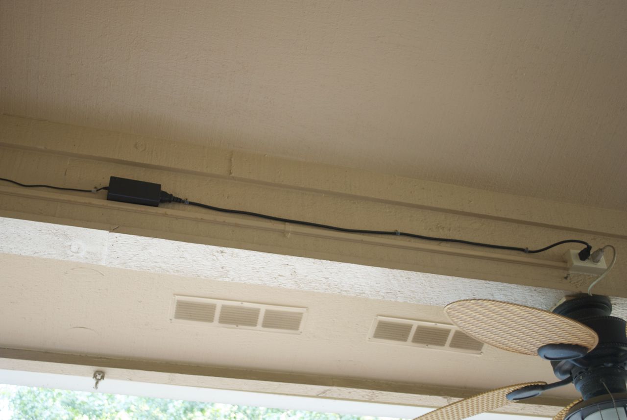
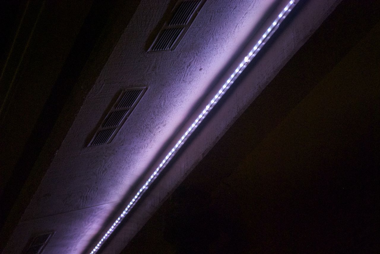
Close-up of under-eave color LED strip
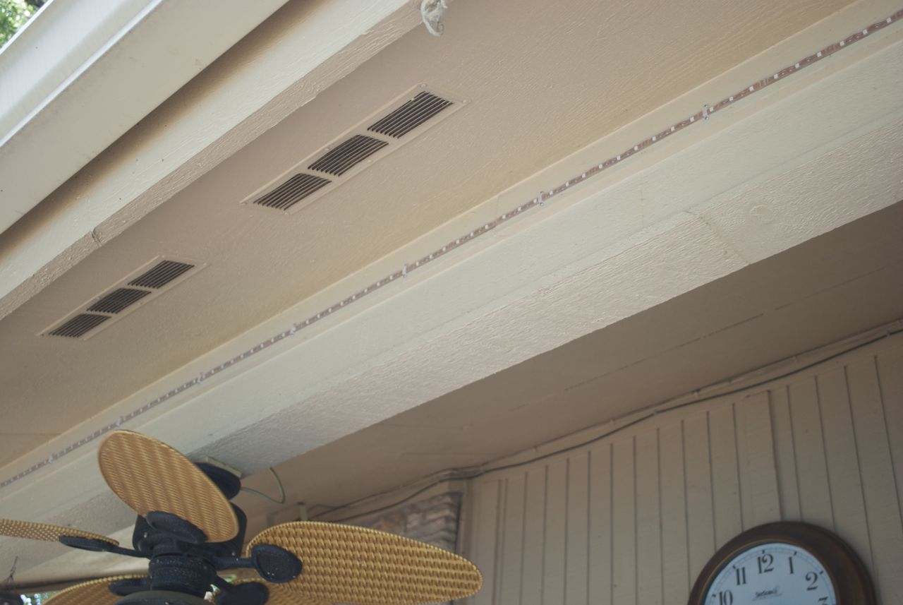
Mounted color LED strip under eaves
I did a bunch of planning to install two of these
strips in the place where I eventually installed the monochrome strips,
but the show stopper was the fact that the deck was already wired with
2-conductor wire, while these colored LED strips needed 4-conductor
wires. The work to re-wire the decks was certainly not worth it for
the added feature of being able to change the colors.
Looking for something to do with this colored LED strip, I thought
about mounting it under the eaves of the house over the new northwest
section of deck, which had no other good lighting. This was not
necessary, but it turened out to be relatively easy to install them, so
I figured I would put them up and see what they looked like. End
result was they looked alright, so I'll leave them there for a while.
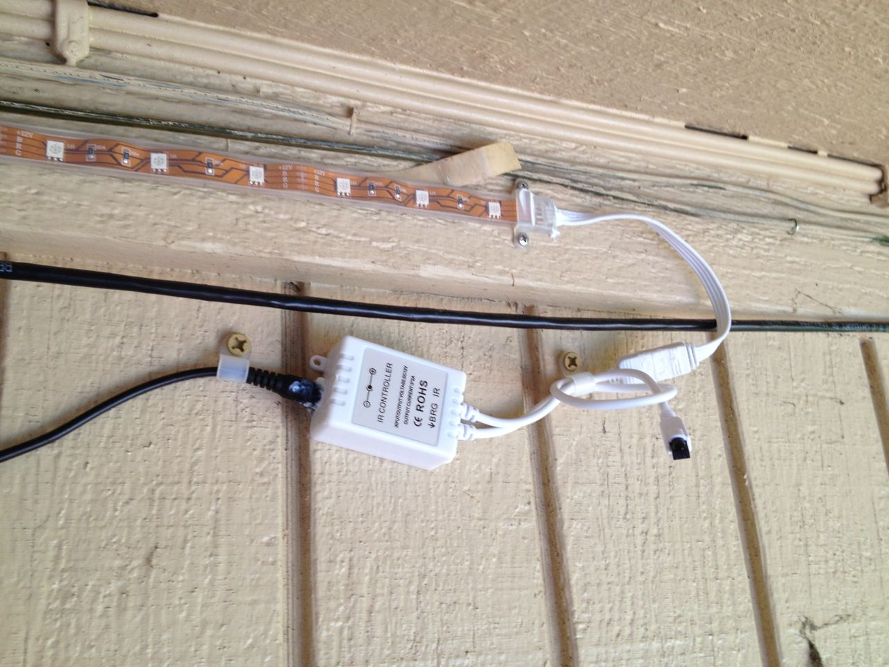
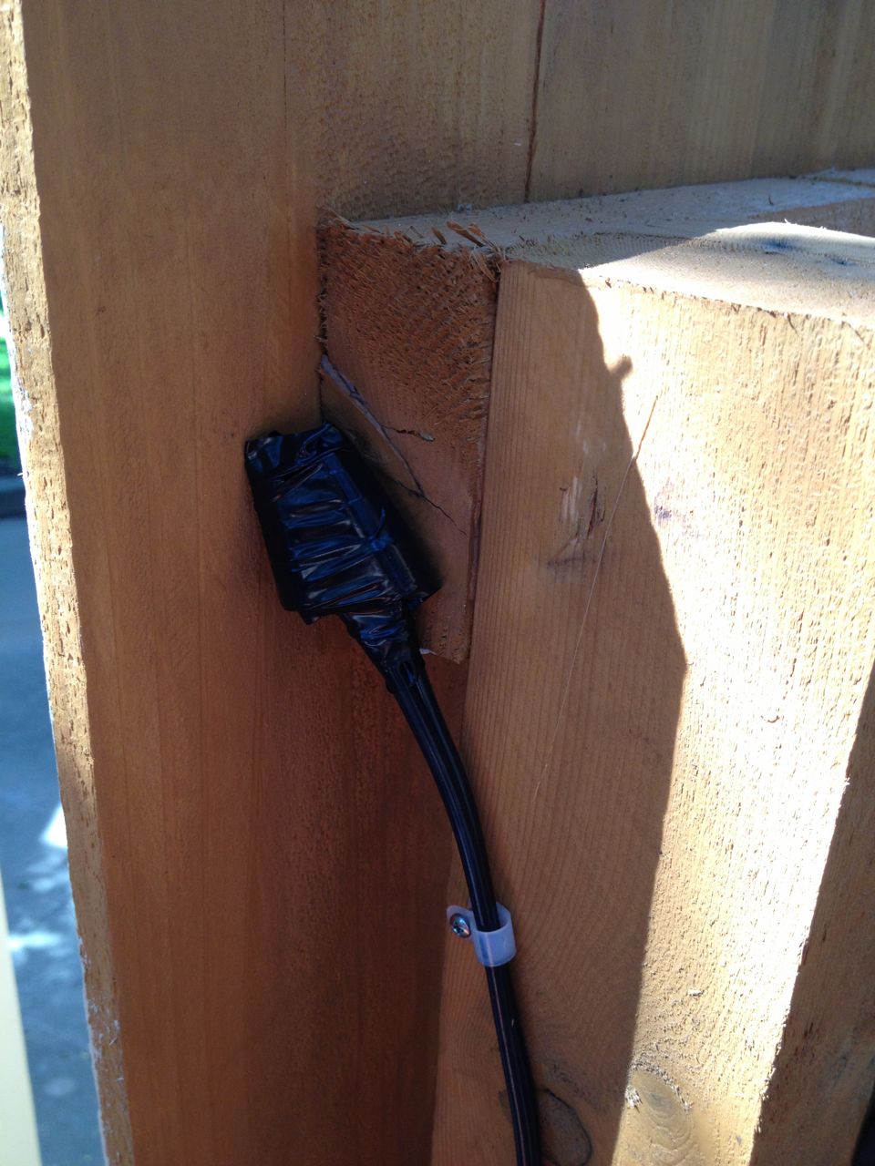
Control box for colored LED strip
Power supply for colored LED strip
One of the things that made it convenient to install the colored LED
strip was the presence of a switched outlet in the exact area where I
planned to install it. This outlet was put in a few years before for a
ceiling fan we have over our covered porch area. It is a two
receptable outlet, both of which are controlled by the same switch, so
I could just plug in the colored LED strip power supply to that. This
is a separate switch from the rest of the deck lights, but that is
actually fine since these would not need to be turned on for most of
the use cases where we wanted the deck lights on. The fan also has a
light, but since both can be turned on and off via a pull cord, there
is the ability to fully control exactly what goes on when the switch is
turned on.
The main problem with the colored LED strip is the same as with the
monochrome strips. The LED strip itself is housed in a nice
weatherproof casing, but all the other components and connectors are
not. In this case, there are two other components: the power supply,
and a little control box that controls the colors (via infrared and a
hand-held remote control. Since I would mounting these under the eaves
of the house, they would not be expposed to too much harsh weather, but
I still went and put silicone sealer in every unsealed junction point
to at least keep some moisture at bay. The wiring is al pretty crude
and ugly, but as long as you don't look up, it is fine.
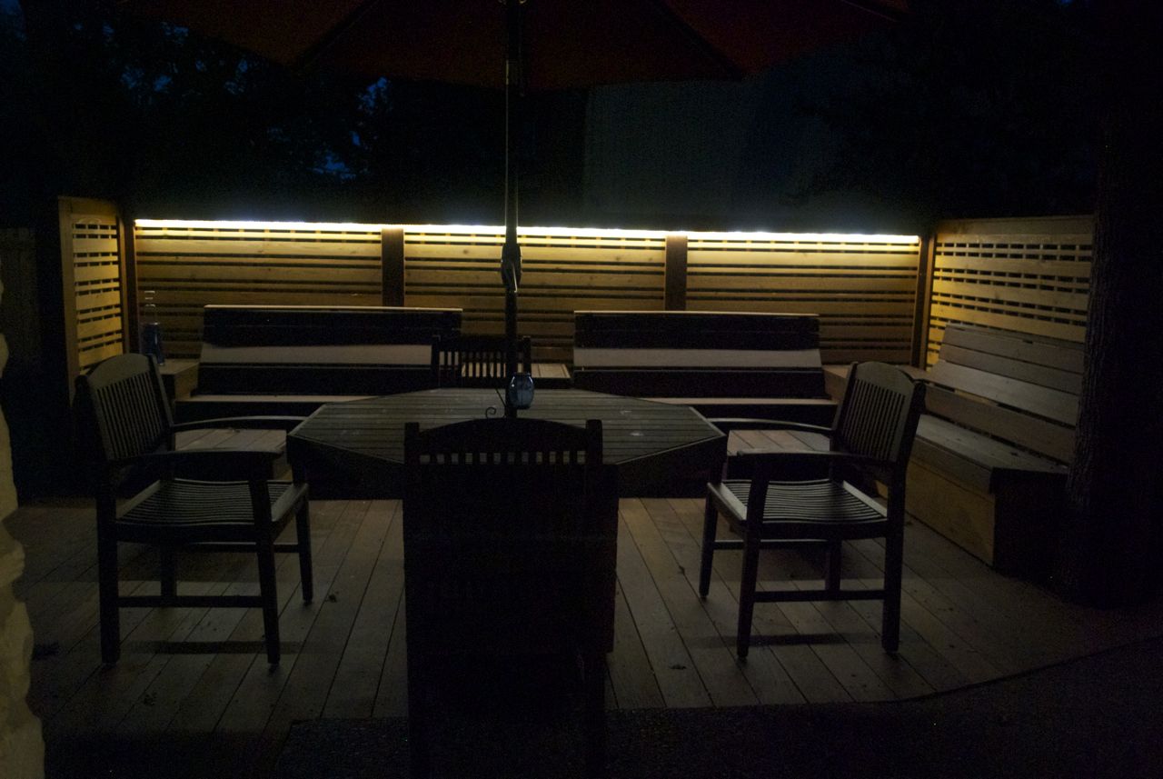
Final Result
I ran out of screws and had not fully worked out how to clean up the
wires and weatherproof things, so there was a few days between getting
this mostly finished and getting it fully finished. Once fully
finished, it was time to take some nice nighttime pictures to try to
capture the effect.
Northeast deck
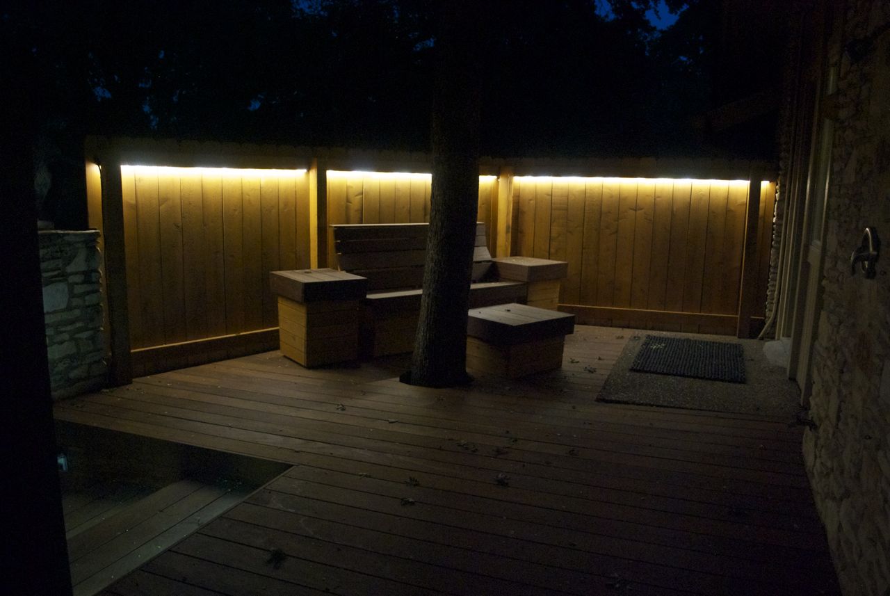
Southeast deck
Colored LED strip
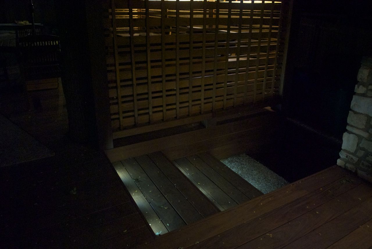
Stair lights looking down
Stair lights looking up
Wide view of decks at night
Color LED light strip